Publication 1764-UM001A-US-P
Installing and Wiring Your Module 3-3
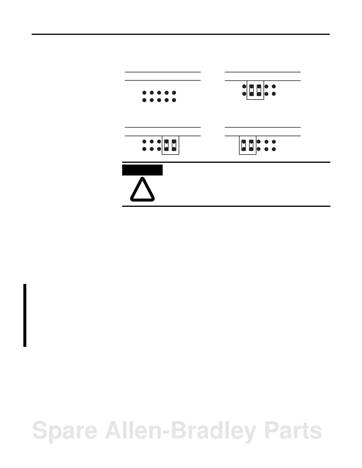
Figure 3.3 JW2 Pin Assignments and Settings
Use the worksheet in appendix B to document the selected jumper setting of
jumper JW2. Documenting your selection provides others with information
necessary to integrate the module with their SLC 500 fixed or modular controllers.
Setting Jumper JW3
Use jumper JW3 to configure the memory module socket for one of the following
optional memory modules:
• 1747-M1, 8K bytes EEPROM (1746-BAS only)
• 1747-M2, 32K bytes EEPROM (1746-BAS only)
• 1747-M3, 8K bytes UVPROM (1746-BAS only)
• 1747-M4, 32K bytes UVPROM (1746-BAS only)
• 1771-DBMEM1, 8K bytes EEPROM (1746-BAS-T only)
• 1771-DBMEM2, 32K bytes EEPROM (1746-BAS-T only)
13579
246810
Daughter Board Daughter Board
Daughter Board Daughter Board
Pin Assignments RS-422
RS-232/-423 (shipped configuration) RS-485
ATTENTION
All other jumper settings for JW2 are illegal and may cause
damage to the module
Spare Allen-Bradley Parts