Publication 1764-UM001A-US-P
3-2 Installing and Wiring Your Module
Setting Jumper JW1
Use jumper JW1 to select one of the following configurations for port PRT1:
• RS-232/423
• RS-422
• RS-485
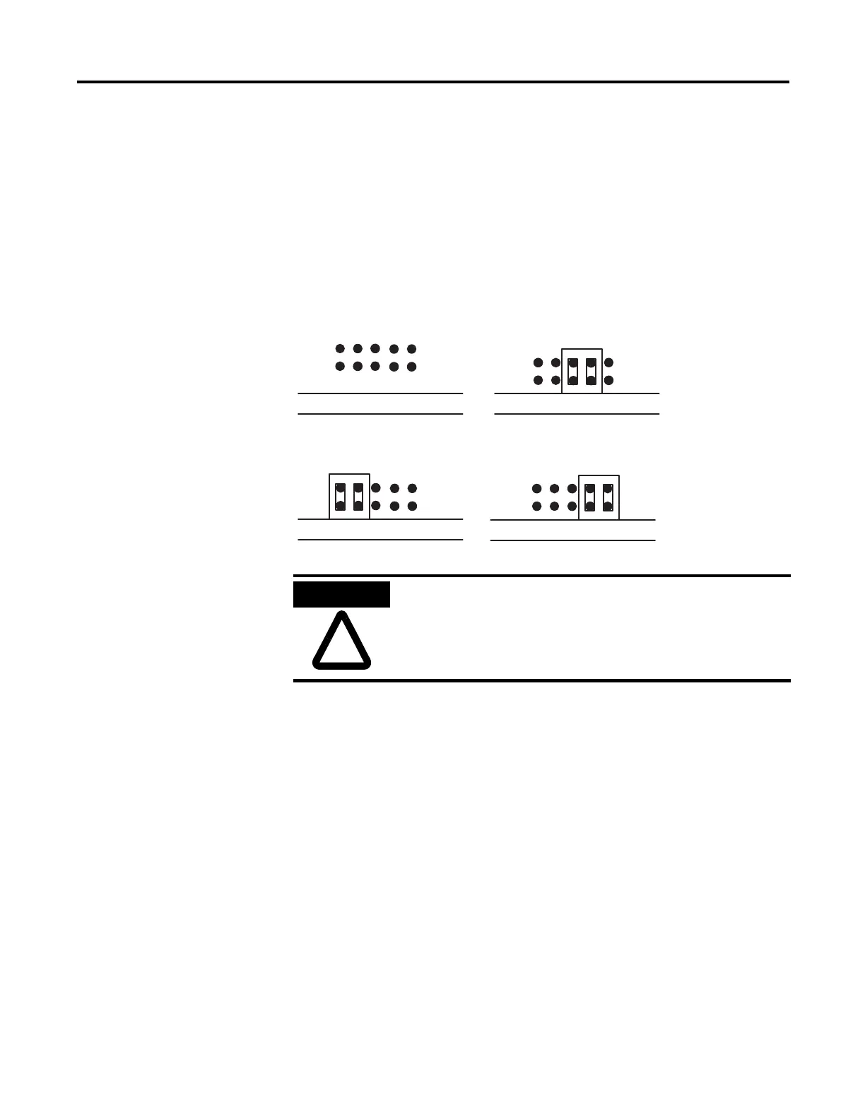
Figure 3.2 JW1 Pin Assignments and Settings
Use the worksheet in appendix B to document the selected jumper setting of
jumper JW1. Documenting your selection provides others with information
necessary to integrate the module with their SLC 500 fixed or modular controllers.
Setting Jumper JW2
Use jumper JW2 to select one of the following configurations for port PRT2:
• RS-232/423
• RS-422
• RS-485
13579
246810
Daughter Board Daughter Board
Daughter Board Daughter Board
Pin Assignments RS-422
RS-232/-423 (shipped configuration) RS-485
ATTENTION
All other jumper settings for JW1 are illegal and may cause
damage to the module.