Publication 1764-UM001A-US-P
3-8 Installing and Wiring Your Module
Wiring diagrams for the RS-232/423 communication mode are shown starting on
page 3-10.
Hardware Handshaking
The module uses the following rules when hardware handshaking is enabled. The
module:
• does not transmit until CTS becomes active
• examines DSR following the receipt of a character. If the DSR is active, the
character is placed in the input queue. If DSR is inactive, the character is
assumed to be noise and is discarded.
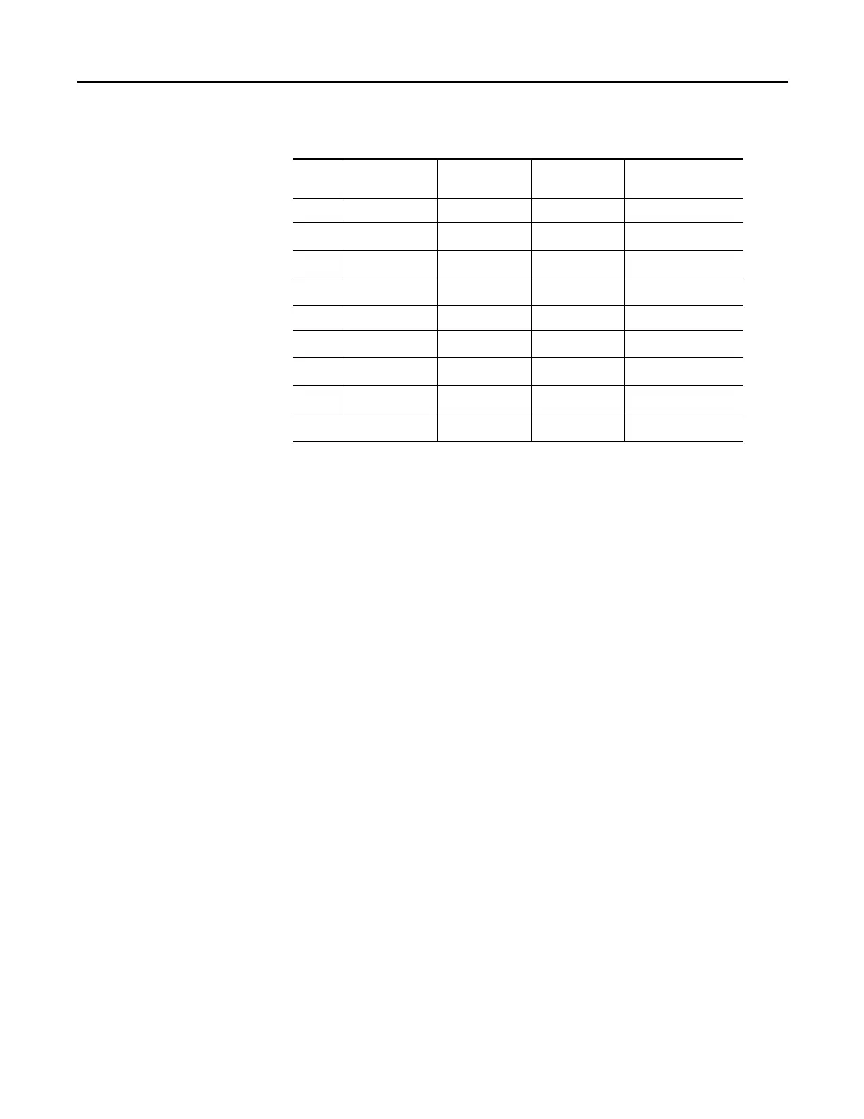
Table 3.1 Ports PRT1 and PRT2 Pin Assignments
Pin RS-232/423 RS-422 RS-485 IBM AT Standard
RS-232 Signals
1 Note 1 422 TXD - TRXD - DCD or CD
2 RXD 422 RXD -
(3)
(3) In RS-485 mode, these pins are still connected to their RS-422 receivers. Do not use these pins in RS-485
mode.
RXD
3TXD
(2)
(2) In RS-422 and RS-485 modes these pins are connected to their RS-423 drivers and receivers. Do not use
these pins in either RS-422 or RS-485 mode.
(2)
TXD
4DTR
(2) (2)
DTR
5 COMMON COMMON COMMON COMMON
6 DSR 422 RXD +
(3)
DSR
7RTS
(2) (2)
RTS
8CTS
(2) (2)
CTS
9
(1)
(1) In RS-423 mode, these pins are still connected to their RS-422 loads. Do not use these pins in RS-423
mode.
422 TXD + TRXD + RI