EasyManuals Logo
Home>Allen-Bradley>Control Unit>SLC 500 BASIC

Allen-Bradley SLC 500 BASIC User Manual

Allen-Bradley SLC 500 BASIC
84 pages
To Next Page IconTo Next Page
To Previous Page IconTo Previous Page
Page #40 background imageLoading...
Page #40 background image
Publication 1764-UM001A-US-P
3-6 Installing and Wiring Your Module
Installing Your module
Once you have unpacked and set the jumpers on your module, you are ready to
install it in your:
SLC 500 fixed controller expansion chassis
SLC 500 modular controller 1746 I/O chassis
Your module may be installed in any open slot of your SLC 500 I/O chassis except
the first slot of the first chassis, which is reserved for the processor module.
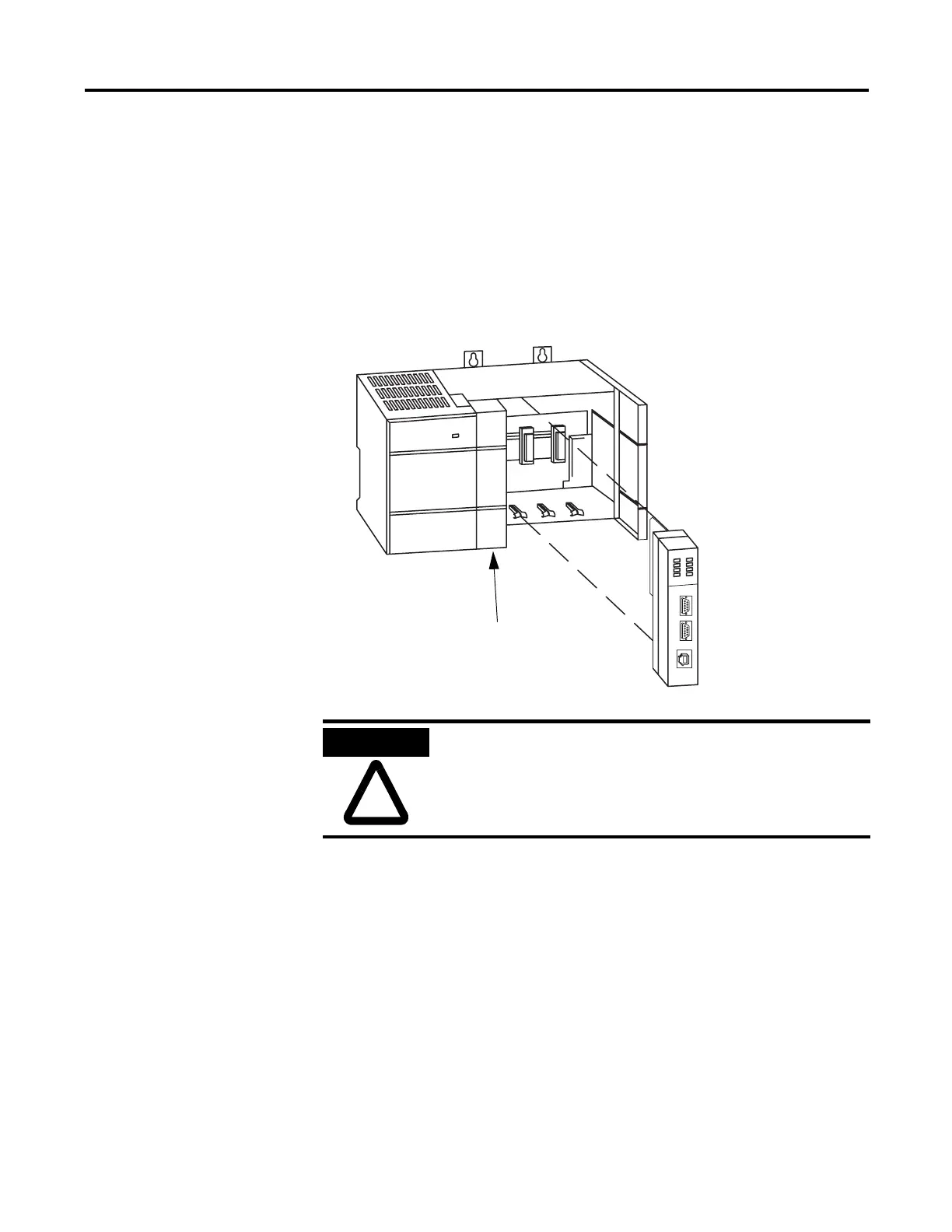
Figure 3.6 Installation in a SLC 500 I/O Chassis
SLC 500 Processor
ATTENTION
Never install, remove, or wire any module with power applied to
the chassis.

Table of Contents

Other manuals for Allen-Bradley SLC 500 BASIC

Questions and Answers:

Question and Answer IconNeed help?

Do you have a question about the Allen-Bradley SLC 500 BASIC and is the answer not in the manual?

Allen-Bradley SLC 500 BASIC Specifications

General IconGeneral
BrandAllen-Bradley
ModelSLC 500 BASIC
CategoryControl Unit
LanguageEnglish

Related product manuals