Publication 1764-UM001A-US-P
Installing and Wiring Your Module 3-11
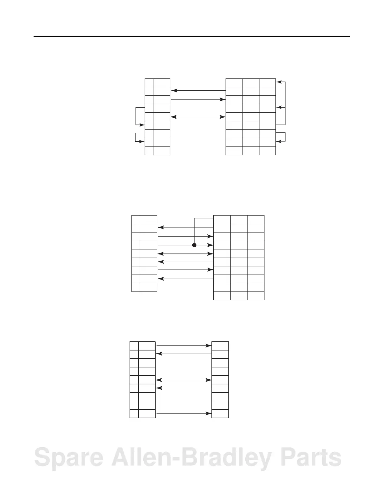
Figure 3.9 RS-232/423 Wiring Diagram - Module to DTE Device (Hardware Handshaking
Disabled)
(1) Connect to the shield of the cable.
(2) Jumpers are only needed if you cannot disable the hardware handshaking on the port.
(3) This is a N.C. for the 1747-KE, 1746-BAS or 1746-BAS-T.
Figure 3.10 RS-232/423 Wiring Diagram - Module to Printer (Hardware Handshaking
Enabled, Standard Printer Adapter Cable)
(1)
(1) The 1747-CP3 Cable works in this application.
(2) Connect to the shield of the cable.
Figure 3.11 RS-422 Wiring Diagram
N.C.1
RXD2
TXD3
DTR4
COM5
DSR6
RTS7
CTS8
N.C.9
DCD
TXD
RSD
DSR
COM
DTR
CTS
RTS
GND
8
2
3
6
7
20
5
4
1
1
3
2
6
5
4
8
7
(1)
(3)
(2)
(2)
(2)
(2)
Basic DTE DTE 9-pin 25-pin
N.C.1
RXD2
TXD3
DTR4
COM5
DSR6
RTS7
CTS8
N.C.9
CD
TXD
RXD
DSR
COM
DTR
CTS
RTS
RI
8
2
3
6
7
20
5
4
22
1
3
2
6
5
4
8
7
9
GND 1
(2)
Basic DTE DTE 9-pin 25-pin
TXD1
RXD2
3
4
COM5
RXD+6
7
8
TXD+9
RXD
TXD
COM
TXD+
RXD+
Basic
Spare Allen-Bradley Parts