Multi-Axis Coordinated Motion Instructions
376 Rockwell Automation Publication MOTION-RM002H-EN-P-February 2018
Ladder Diagram
When MCTO is active, with a move to Cartesian positions X = 7.361, Y = -4.25,
Z = -928.18, Rx = 180, Ry = 30 and Rz = -30, the MCTO computes the
corresponding Joint angle as shown in the following diagram.
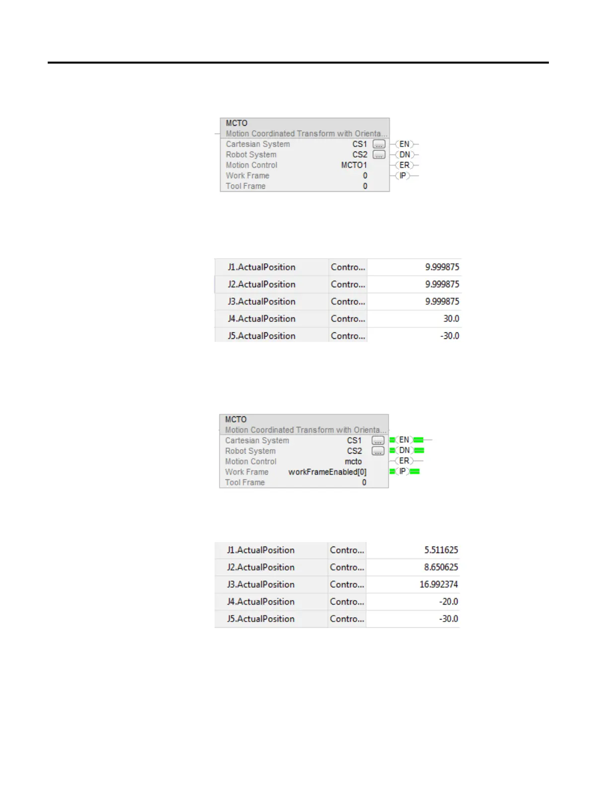
Consider the same MCTO, with work frame offsets enabled for X = 50, Y = 50
and Rz = 50. Now MCTO will compute the Cartesian positions with respect to
the new work frame.
When a move is programmed to the same end position, the corresponding joint
positions are as shown in the following diagram.
 Loading...


