Multi-Axis Coordinated Motion Instructions
Rockwell Automation Publication MOTION-RM002H-EN-P-February 2018 379
Inputs
The following table explains the instruction inputs. The inputs may be field device
signals from input devices or derived from user logic.
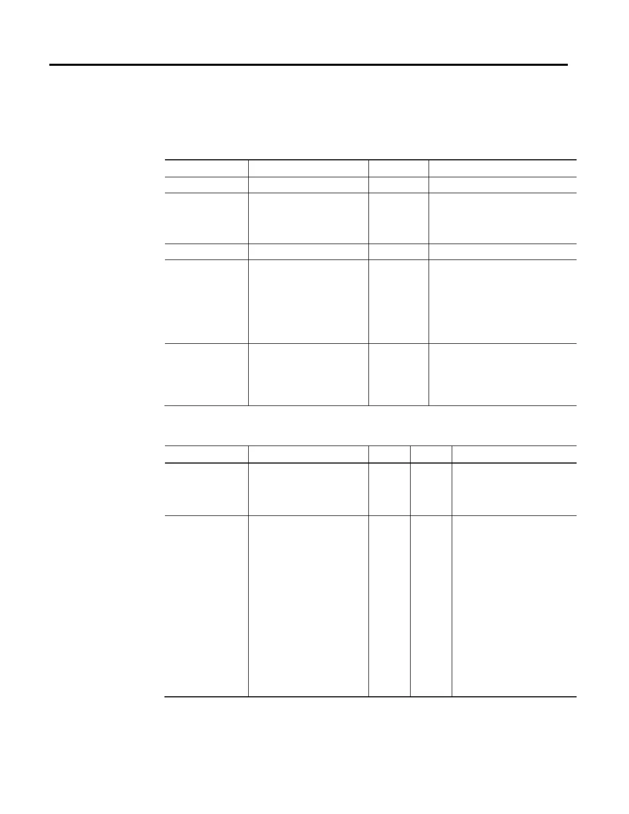
Operand Data Type Format Description
Path PATH_DATA Tag See PATH_DATA Structure
Length DINT Immediate Tag This input is immediate and indicates the length
of the PATH_DATA input.
Tip: Set the length to 1. Values greater than 1 are
reserved for future use.
Dynamics DYNAMICS_DATA Tag See DYNAMICS_DATA Structure
Lock Position REAL Tag Position on the Master Axis where a Slave should
start following the master after the move has
been initiated on the slave axis coordinate
system.
Tip: Lock Position is only valid when the MCPM
instruction is used in Master Driven Speed Control
mode.
Lock Direction UINT32 Tag Specifies the conditions when the Lock should be
activated.
Tip: Lock Direction is only valid when the MCPM
instruction is used in Master Driven Speed Control
mode.
PATH_DATA Structure
Operand Scroll, List, or Check Box Data Type Default Notes
Interpolation Type List of Point-to-Point (0) Continuous
Path Linear (1)
DINT 0 Point-to-point move
2
Continuous Path Linear
See Interpolation Type related topics
below.
Position [X, Y, Z, Rx, Ry, Rz] List of constant or variable REAL [9] 1 0 [X,Y.Z] in Coordination Units,
[Rx, Ry, Rz] X-Y-Z fixed angle format in
degrees
Index 0: X
1: Y
2: Z
3: Rx
4: Ry
5: Rz
6: *
2
7: *
2
8: *
2
See Position related topics in the
following section.
 Loading...


