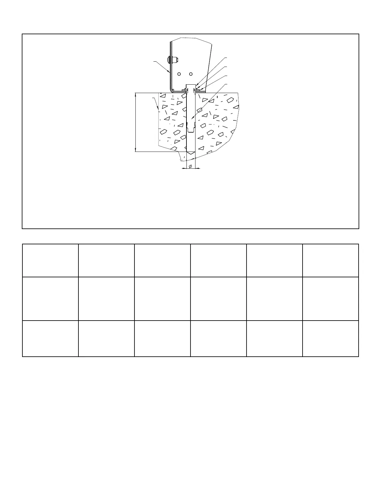
1. Plinth
2. Anchor bolt
3. Anchor washer
4. Washer
5. Anchor Body
6. Floor
Figure 16
Machine
Machine with
Plinth Collec-
tor Anchoring Bolt
Tightening Mo-
ment (Nm /
lbf.ft)
L (Minimum
Hole Depth) (in
[mm] )
Ø (Hole Diame-
ter) (in [mm] )
6.5 kg / 14 lb / 65
L, 7.5 kg / 20 lb /
75 L, 10.5 kg / 25
lb / 105 L, 13.5
kg / 30 lb / 135 L
Must be anchored
M10x60 (A4-70) 40 / 29 3.15 [80] 0.59 [15]
18 kg / 40 lb / 180
L, 24 kg / 55 lb /
240 L, 28 kg / 70
lb / 280 L
Must be anchored M12x80 (A4-70) 60 / 44 3.94 [100] 0.71 [18]
Table 10
1. Check the position of the machine base frame with a water
level.
2. Drill a hole for the anchoring bolt based on the required ma-
chine placement. Refer to Figur
e 16 .
3. Remove washer and bolt from the anchoring bolt and install
anchoring bolt into the pre-drilled hole.
4. Install the plinth base.
5. Install washer and nut. Tighten nut.
Installation
©
Copyright, Alliance Laundry Systems LLC -
DO NOT COPY or TRANSMIT
40 Part No. D2418ENR6




 To Next Page