Section 4
4 - 41
14
15
15
15
5
4
9
16
16
38
30
31
29
4
5
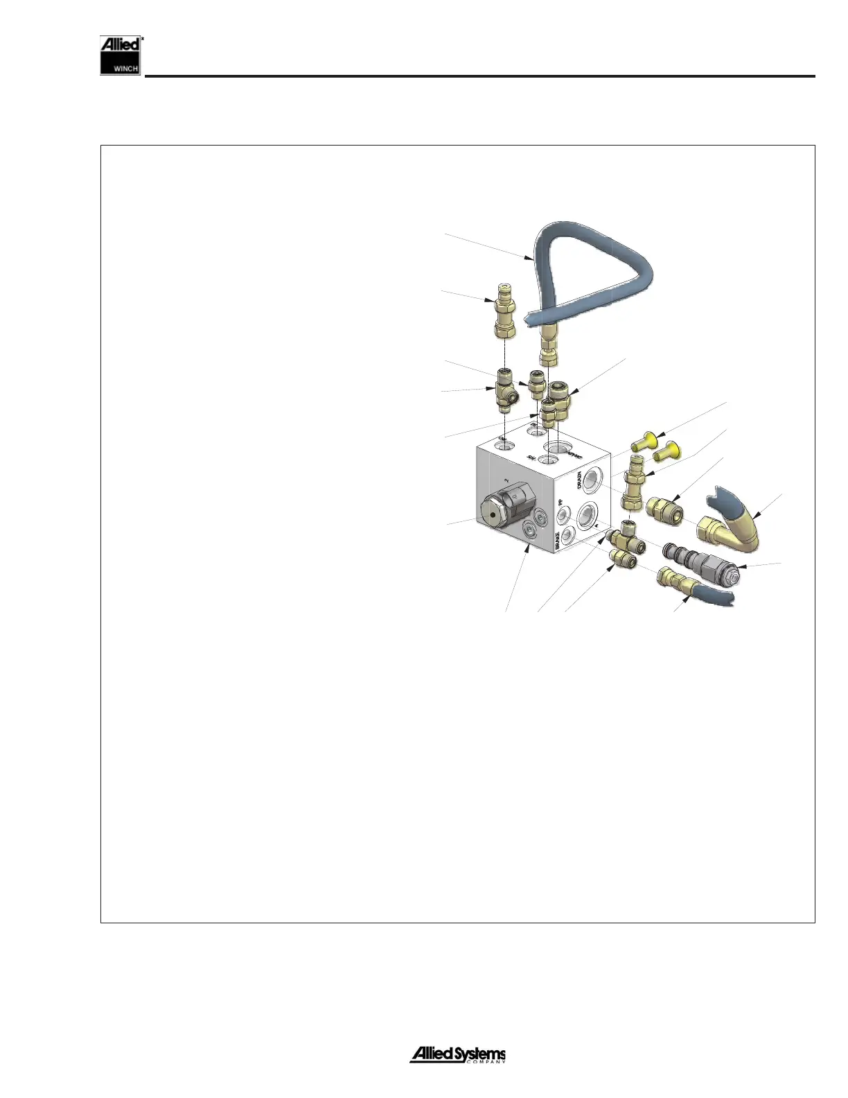
Detail at
Control Manifold
39
1. Capscrew
2. Washer
3. Nut
4. Fitting, Tee
5. Coupler, Male
6. Fitting, El
7. Fitting, El
8. Tube Assembly
9. Capscrew
10. Washer
11. Cross Port Relief Manifold
12. Relief Valve
14. Control Manifold
15. Fitting
16. Fitting
17. Fitting, Tee
18. Fitting, El
19. Fitting, Tee
20. Fitting
21. Temperature Switch
22. Counterbalance Valve Manifold
23. Counterbalance Valve
24. Fitting
25. Fitting, El
26. Fitting, Tee
27. Fitting, El
28. Fitting
29. Hose Assembly (FS port on Control Manifold to FS port on Bulkhead)
30. Hose Assembly (Brake port on Control Manifold to Brake)
31. Hose Assembly (Drain Port on Control Manifold to Motor Drain)
32. Hose Assembly (Cross Port Relief Manifold to Port 2 on Counterbalance Valve)
33. Hose Assembly (Cross Port Relief Manifold to tee fi tting on Motor Port B)
34. Hose Assembly (Port 3 on Counterbalance Valve Manifold to tee fi tting on Motor
Port B)
35. Capscrew
36. Fitting
37. Hose Assembly (FS port on Bulkhead to Freespool Shifter Fork)
38. Directional Valve Cartridge
39. Freespool Valve Assembly
Figure 4-12 Hydraulic System Components, Rescue Winch_2
 Loading...