Section 4
4 - 53
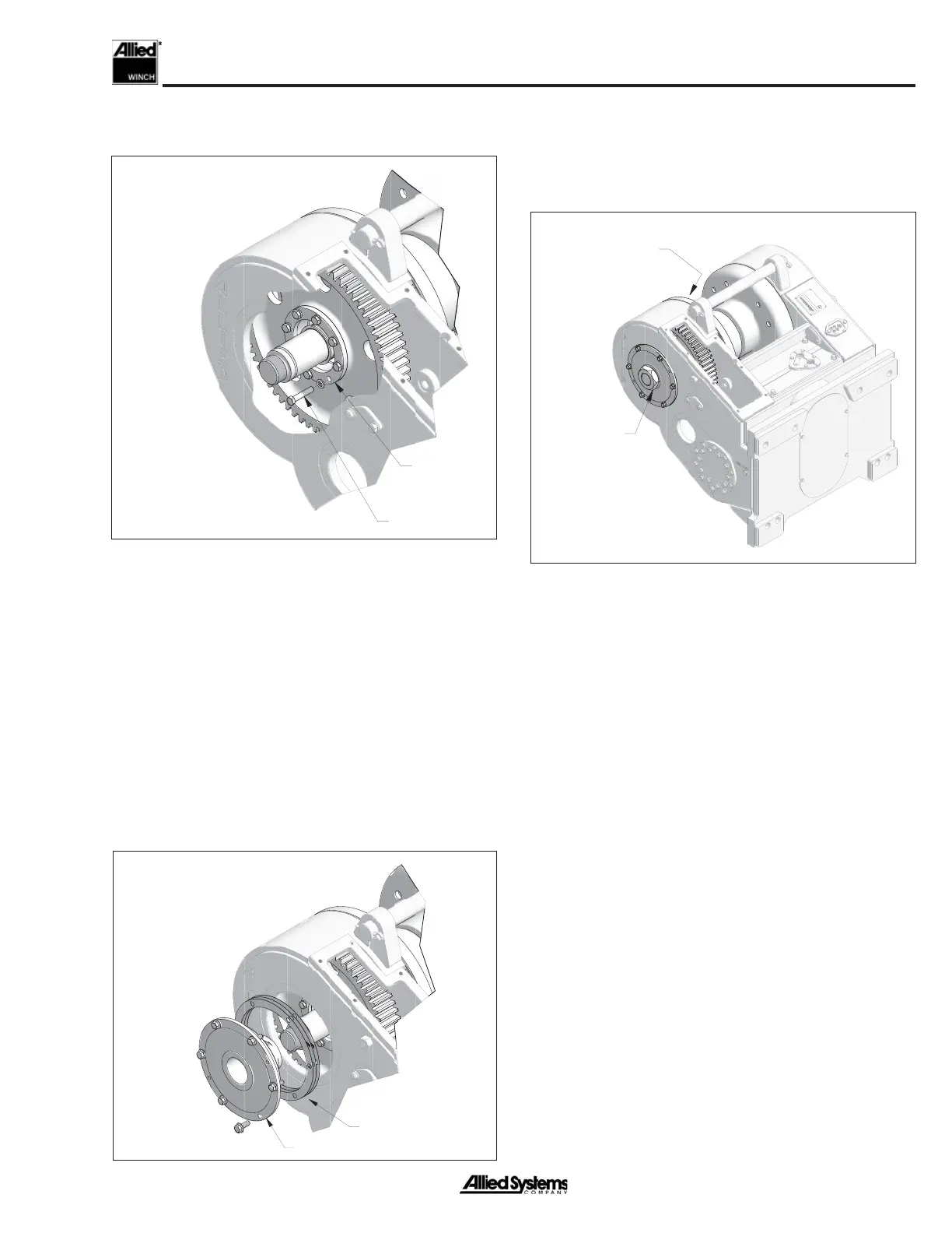
13. Install retainer plate using the eight special cap-
screws. Tighten capscrews to 90 ft-lbs (12 kg-m).
NOTE: Capscrews cannot be installed unless drum
gear and drum adapter have been aligned as indicated
in Step 8.
14. Set drum retainer into place and tighten capscrews
(do not tighten to fi nal torque). Measure gap between
retainer and winch frame in three places around the
retainer. Add the three indications and divide by three
to add obtain the average gap. Assemble shim pack
to provide a net fi t with ± 0.005 inch (0.1288 mm)
tolerance.
15. Coat winch frame and bearing retainer with silicone.
Install drum shaft O-ring. Install fi nalized shim pack
(determined in step 15). If intermediate shaft as-
sembly not installed, install before retainer.
Note: Part of
frame shown
removed for
clarity
Retainer
Plate
Capscrew
Drum Retainer
Shim Pack
Shaft Nut
Both Sides
Drum-to-Adapter
Capscrews
(Not Shown)
16. Secure retainer with capscrews and lockwashers.
Tighten capscrews to 75 ft-lbs (10 kg-m).
17. Coat shaft nut threads with anti-seize. Install both
shaft nuts and torque to 400 ft-lbs (55 kg-m).
18. Tighten drum-to-adapter capscrews to 155 ft-lbs (21
kg-m) torque.
 Loading...