Section 4
4 - 5
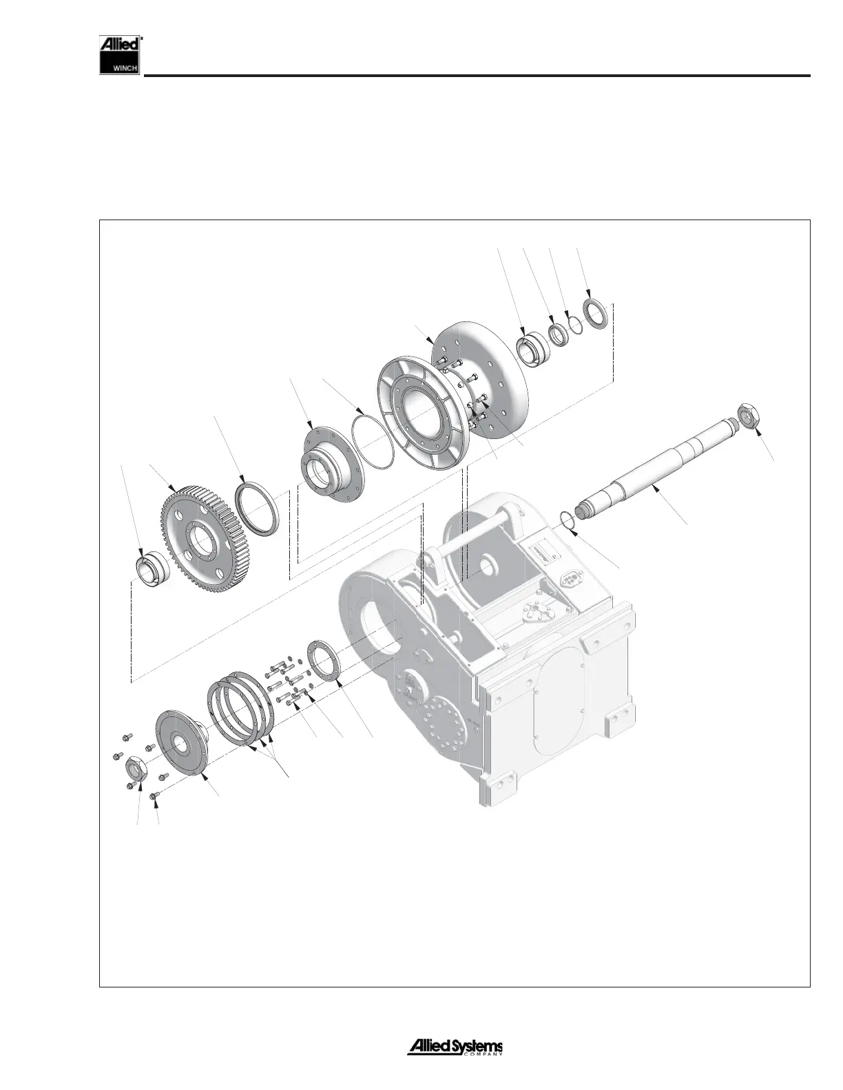
Figure 4-2 Location of Drum and Drum Shaft Components
Drum Shaft & Drum Removal
Figure 4-2 shows the location of drum and drum shaft
components. Do not attempt to remove heavy components
such as the drum or drum gear by hand. Always use a lift-
ing device and the recommended attachments whenever
possible. To remove the drum gear it will be necessary to
fi rst remove the intermediate shaft (see Intermediate &
FREESPOOL Shaft Removal section).
1
2
3
4
4
5
6
7
8
8 9
10
11 12
13
14
15 16
17
18
19
20,21,22
1. Drum
2. Drum Shaft
3. Bearing Retainer
4. Locknut
5. Adapter
6. Capscrew
7. Thimble
8. Roller Bearing
9. Drum Gear
10. Capscrew
11. Washer
12. Retainer Plate
13. Capscrew
14. Oil Seal
15. Oil Seal
16. O-Ring
17. Oil Seal
18. O-Ring
19. O-Ring
20. Shim
21. Shim
22. Shim
 Loading...