EasyManuals Logo

Allied Systems Allied H6G Series User Manual

Default Icon
122 pages
To Next Page IconTo Next Page
To Previous Page IconTo Previous Page
Page #69 background imageLoading...
Page #69 background image
Section 4
4 - 9
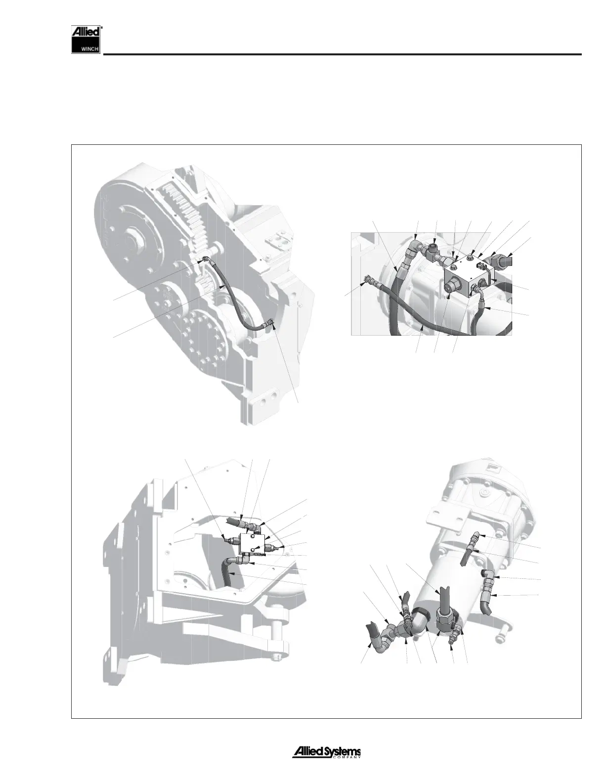
Hydraulic System Disassembly, Rescue
Winch
Disconnecting the hoses is necessary in order to remove
the motor shaft assembly. For easier re-installation, be
15
37
36
Detail at Freespool
Shifter Fork
36
29 23
222417
1832
1,2,3
21
8
34
15
27
28
Detail at Counterbalance
Valve Manifold
6
7
30
55
625
8
24
26
33
31
3419
Detail at Motor
and Brake
11
13
13
12
12
20
2033
32
10,35
Detail at Cross Port
Relief Manifold
sure to clearly mark the hose ends of any hoses removed
with their corresponding ports.
Figure 4-3 Hydraulic System Components, Rescue Winch_1

Table of Contents

Questions and Answers:

Question and Answer IconNeed help?

Do you have a question about the Allied Systems Allied H6G Series and is the answer not in the manual?

Allied Systems Allied H6G Series Specifications

General IconGeneral
BrandAllied Systems
ModelAllied H6G Series
CategoryWinches
LanguageEnglish

Related product manuals