Engine Assembly
Page 1 of 4
In Baler Parts Manual
Engine Assembly
Page 1 of 4
Item Part No. Qty Description Item Part No. Qty Description
906188 Assembly, Engine
1 * 903907 1 . Control Box Assembly
2 CBL1743180 1 . Cable, Control
3 CLH0001084 1 . Clutch
4 CLV1756012 1 . Clevis Assembly
5 * 258766 1 . Engine, Deutz 4 Cylinder
6 900537 1 . Arm Extension Weldment
7 EXH0013806 1 . Tube, Exhaust
8 900534 1 . Plate,Mounting
9 F000007699 1 . Pulley, Motor
10 MNT0018340 1 . Belly Pan Weldment
11 F000007013 1 . Bracket
12 252601 2 . Fitting
13 231486 1 . Set Screw
14 STS5000750 1 . Set Screw
15 SHD0028273 1 . Plate,Shield
17 R13811085 4 . Capscrew
18 Y09C-M0616 1 . Capscrew
20 Y09C-M1030 22 . Capscrew
25 221771W 8 . Washer
26 234589 22 . Lockwasher
27 292680W 1 . Washer
28 296420W 18 . Hard Washer
29 220044 1 . Hex Nut
32 223587 4 . Nut, Esna
33 235620 2 . Nut, Esna
37 R13810989 2 . Capscrew
38 R13811014 2 . Capscrew
39 232939 2 . Nut, Esna
40 905246 16 . Washer, Fender
41 904697 1 . Restrictor
42 201431 1 . Hose Clamp
43 CBL0000126 1 . Cable Assembly,Battery
44 906659 1 . Fitting
45 906660 1 . Hose Assembly
46 236077 3GL . Oil, Engine
47 293613W 1 . Capscrew
48 WLKM000080 1 . Lockwasher
49 WCTM100080 1 . Washer
50 209588 1 . Clip
* See Separate Coverage
Rev A
9
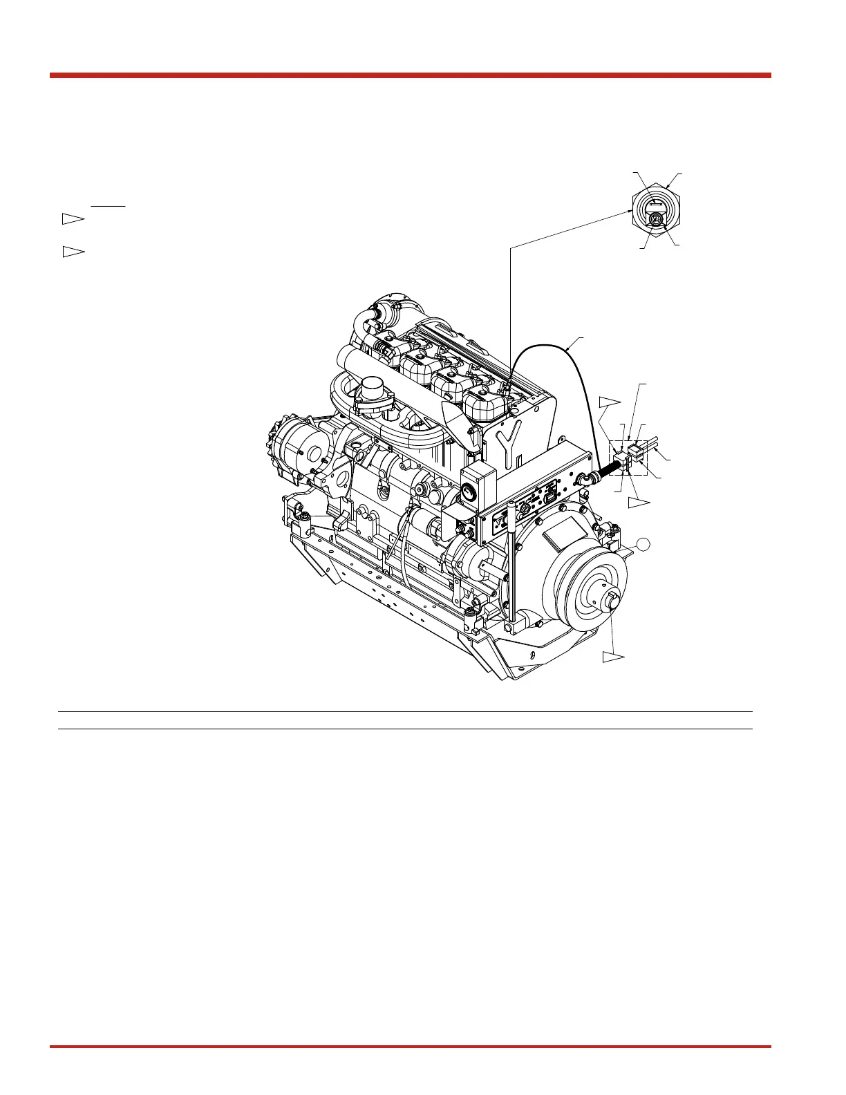
NOTES:
AFTER INSTALLING PULLEY CUT AWAY EXCESS SHAFT FROM
CLUTCH. REMAINING SHAFT SHOULD EXTEND PAST PULLEY
APPROXIMATELY 0.25".
TRIM SIDE CONNECTING TAB BEFORE TAPING.
SET FINAL TOP ENGINE RPM AT FULL THROTTLE TO 2200 TO 2250
(84 TO 86 PLUNGER STROKES PER MINUTE).
SET FINAL LOW ENGINE RPM AT FULL THROTTLE TO 1000 TO
1025 (33 TO 35 PLUNGER STROKES PER MINUTE).
ALL MEASUREMENTS ARE TO BE TAKEN AT THE PULLEY OFF
THE ENGINE. REFER TO ENGINE ASSEMBLY NOTES (
ITEM 0, PN
906640) FOR MORE DETAILED INSTRUCTIONS.
1-1
1-1
RED / WHITE
16 GA WIRE
RED
YELLOW
WHITE
WHITE
CONNECT TO ENGINE WIRE
HARNESS, THEN TAPE
CONNECTORS TOGETHER.
WIDE TAB
NARROW TAB
TEMP SENSOR
CONNECT WIRE END
TO NARROW TAB.
ENGINE HARNESS
1-2
1-2
1-2
1-3
1-4
1-5
20
89-096 Rev: 11-2016
 Loading...