EasyManuals Logo

Allied Telesis AT-9924T User Manual

Allied Telesis AT-9924T
65 pages
To Next Page IconTo Next Page
To Previous Page IconTo Previous Page
Page #31 background imageLoading...
Page #31 background image
30 x900 Series Switch and SwitchBlade
®
x908
C613-03092-00 REV J
Cables
This section describes the following:
RS-232 Terminal and Modem Cables
Cables for RJ-45 Ethernet LAN Interfaces
Cables for Stacking
Cable Guidelines
Troubleshooting Cables
RS-232 Terminal and Modem Cables
The terminal and modem cables described in this section are:
RS-232 RJ-45 to DB9 female terminal cable
DCE RS-232 terminal port RJ-45 to DB9 male modem cable
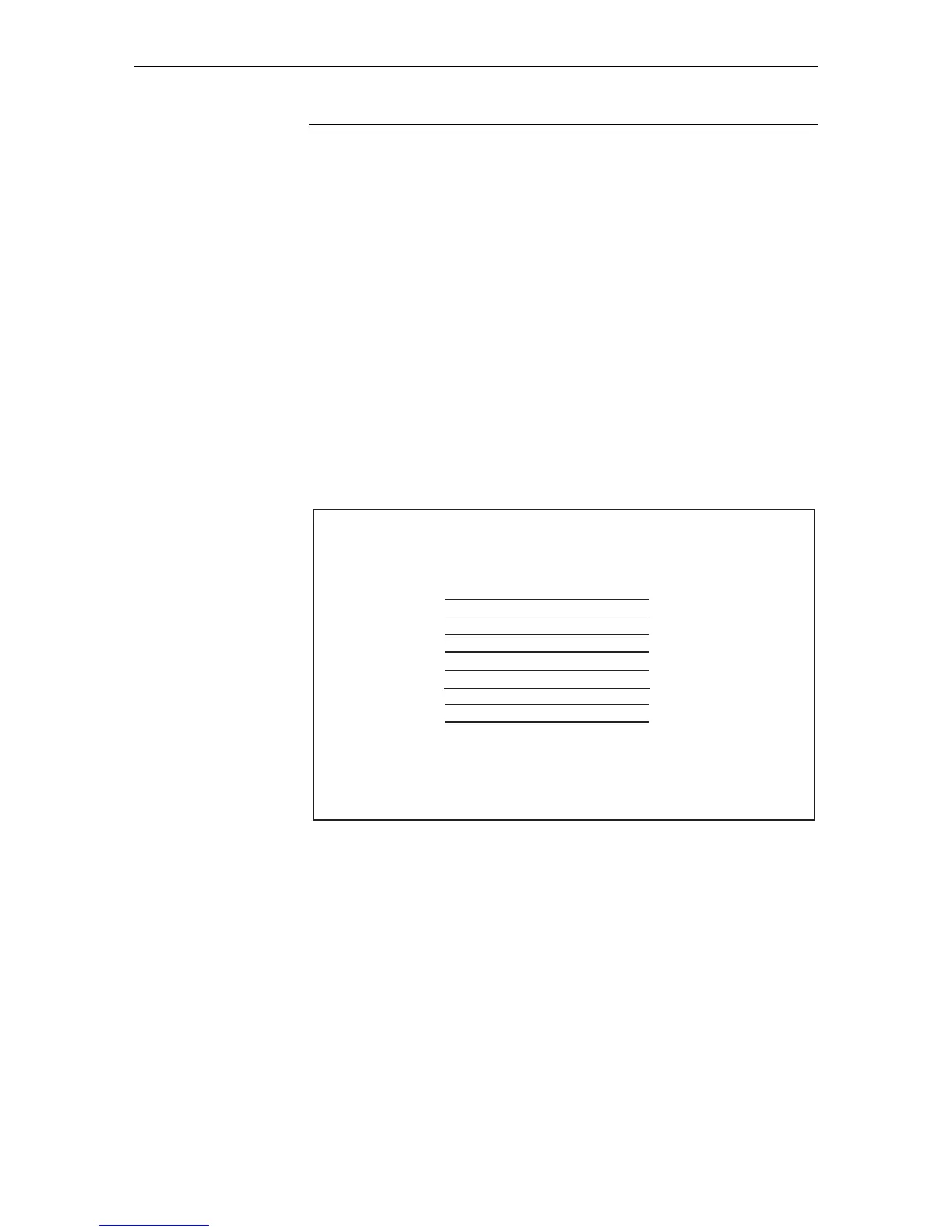
Figures in this section show pin wiring diagrams to connect a standard VT100
compatible terminal or modem to ASYN0.
RJ-45 to DB9
female terminal
cable
Note
This cable supplied as part number C855-84903-00.
Now at version B.
RJ45DB9F_x900
1
2
3
4
5
6
7
8
9 not connected
4
3
6
7
5
2
8
1
RJ-45
(to switch)
DB9 Female
(to terminal)

Table of Contents

Other manuals for Allied Telesis AT-9924T

Questions and Answers:

Question and Answer IconNeed help?

Do you have a question about the Allied Telesis AT-9924T and is the answer not in the manual?

Allied Telesis AT-9924T Specifications

General IconGeneral
BrandAllied Telesis
ModelAT-9924T
CategorySwitch
LanguageEnglish

Related product manuals