Hardware Reference 35
C613-03092-00 REV J
Power Supply Units (PSUs) and Fans
Depending on the model, single or dual PSUs can be fitted on the rear of the
switch, as either AC or DC. Some models also have fan-only modules (FOM)
and chassis fans.
Each PSU and FOM contains an EPROM chip that contains information, such
as the type of module, serial number, and revision of the PSU. This information
is available through the command line interface (CLI).
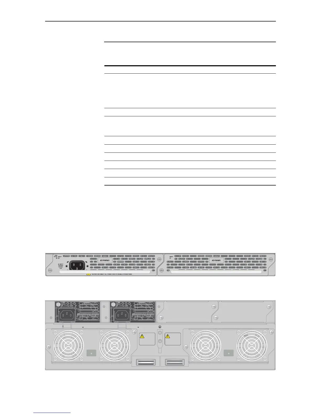
How to install a PSU or fan in the switch is described in the Removable Power
Supply and Fan Installation Guide.
PSU and FOM installed in an x900-24XT switch
PSUs and chassis fans installed in a SwitchBlade x908
Model Description
AT-8948
x900-48FE
x900-48FS
AT-9924T
AT-9924SP
Supports 1 PSU and 1 FOM, or 2 PSUs.
A second PSU is available for optional redundancy. When two are
fitted, they must be the same type of current, either AC or DC.
When there is just one PSU in an AT-9900 series switch, it must be in
Bay
2 for optimised cooling.
x900-12XT/S Supports 1 fixed PSU.
AT-9924Ts
x900-24XT
x900-24XS
Supports 1 PSU and 1 FOM, or 2 PSUs.
A second PSU is available for optional redundancy.
SwitchBlade x908 Supports 2 System PSUs and 2 chassis fan modules.
AT-PWR01 AC or DC power supply unit.
AT-PWR02 AC power supply unit.
AT-PWR05 AC or DC power supply unit.
AT-FAN01 Fan-only module (FOM).
AT-FAN03 Chassis fan module.
 Loading...