Hardware Reference 31
C613-03092-00 REV J
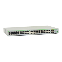
RJ-45 to DB9
male modem cable
For more information on pin assignments for the RS-232 port, see “RS-232
Terminal Port” on page 19.
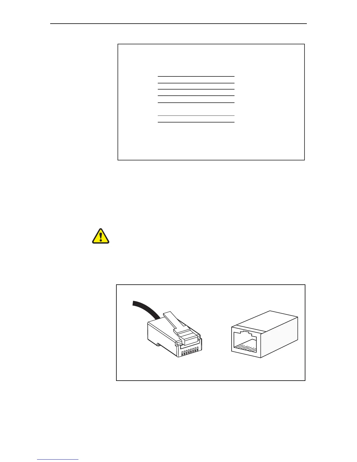
Cables for RJ-45 Ethernet LAN Interfaces
A twisted pair cable with four pairs and RJ-45 connectors must be used for
10BASE-T/100BASE-TX/1000BASE-T connections.
Caution Do not plug a phone jack into an RJ-45 switch port because you could
damage the switch. Use only twisted pair cables with RJ-45 connectors.
Pin assignments Each pair of twisted pair cables is identified by related colours. For example,
one wire might be red and the related wire would be red-and-white stripe. An
RJ-45 connector must be fitted to both ends of the cable. The following diagram
shows RJ-45 connectors and the pin layout.
Note
Cable version 1.0
1
2
3
4
5
6 not connected
7
8
9 not connected
RJ-45
(to switch)
DB9 Male
(to modem)
RJ45DB9M_x900
8
1
4 not connected
5
2
3
6
7
1
 Loading...