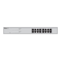
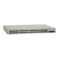
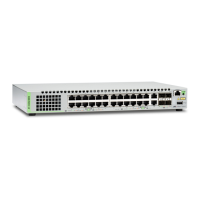
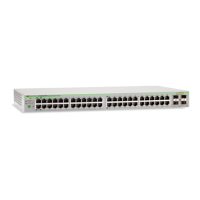
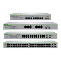
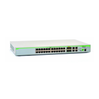
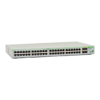
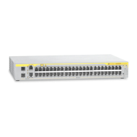
AT-GS908M, AT-GS916M, and AT-GS924M Switches Installation Guide
17
LEDs The following lists the switch LEDs:
Power LED; refer to “POWER LED” on page 23.
Fault LED; refer to “FAULT LED” on page 24.
Standby LED; refer to“STANDBY LED” on page 24.
Speed and Duplex Mode LEDs; refer to “MODE LEDs” on page 24.
Speed/Duplex and Link/Activity LEDs for the twisted-pair ports;
refer to “Port LEDs” on page 25.
Link/Activity LEDs for the SFP slots; refer to “SFP Slot LEDs” on
page 26.
Installation
Options
The AT-GS900M Series switches can be installed in the following ways:
Rack mounted in a 19-inch equipment rack
Mounted on a desk or tabletop
If installing the switch in an equipment rack, rack mounting equipment
provided with the switch depends on the switch model as follows:
AT-GS908M: rack mounting equipment must be purchased
separately. The rack mounting kit model number is AT-RKMT-J05.
AT-GS916M and AT-GS924M: rack mounting hardware is included
in the shipping package.
MAC Address
Table
Here are the basic features of the MAC address table:
Storage capacity up to 8KB MAC address entries
Automatic learning and aging
 Loading...

