AT-GS908M, AT-GS916M, and AT-GS924M Switches Installation Guide
23
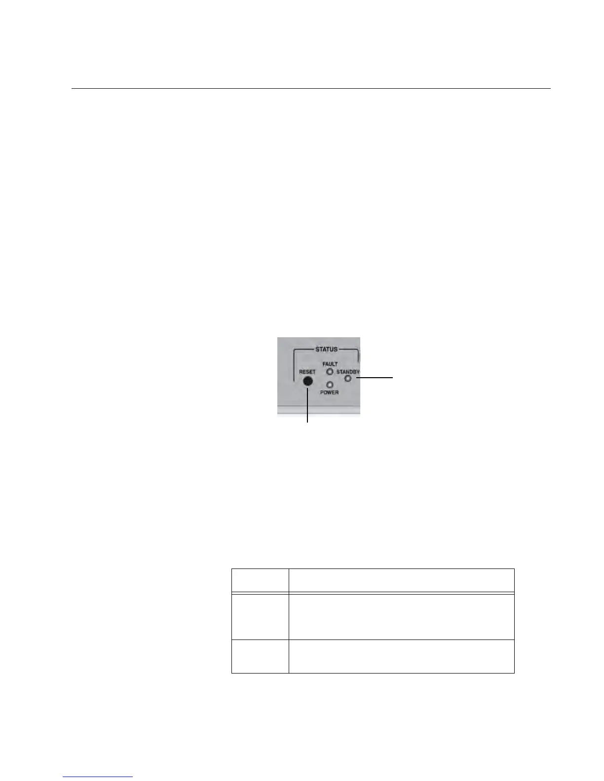
LEDs
There are four types of LEDs on the AT-GS900M Series switches:
“STATUS LEDs”
“MODE LEDs” on page 24
“Port LEDs” on page 25
“SFP Slot LEDs” on page 26
STATUS LEDs STATUS LEDs display the status of the switch.
STATUS LEDs are as follows:
“POWER LED”
“FAULT LED” on page 24
“STANDBY LED” on page 24
The STATUS LEDs are located on the left side of the front panel of the
switch. See Figure 3.
Figure 3. STATUS LEDs
POWER LED
The POWER LED reports the status of AC power.
Table 2 describes the states of the POWER LED.
Table 2. POWER LED Functional Description
State Description
Off Indicates either the switch is not receiving
AC power or the AC input power is operating
outside the normal range.
Steady
Green
The switch is receiving AC input power and is
operating normally.

 Loading...