AT-GS908M, AT-GS916M, and AT-GS924M Switches Installation Guide
41
Installing the Switch in an Equipment Rack
The AT-GS916M and AT-GS924M rack mounting hardware is
included in the shipping package. However, the AT-GS908M rack
mounting equipment must be purchased separately. The rack
mounting kit model number is AT-RKMT-J05.
To install the switch in a standard 19-inch equipment rack, perform the
following procedure:
1. If the rubber feet are attached to the bottom of the switch, remove
them using a flat-head screwdriver.
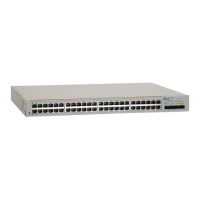
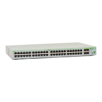
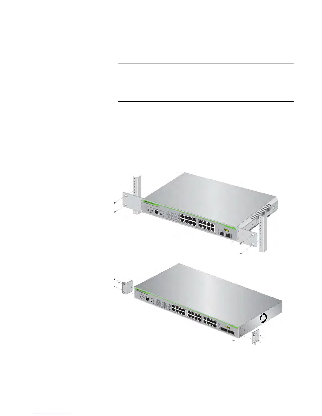
2. Attach the two rack mount brackets to the sides of the switch using the
bracket screws that come with the unit. See Figure 10.
Figure 10. Attaching the Rack-Mount Brackets to the Switch

 Loading...