EasyManuals Logo

Allied Telesis AT-GS900M Series Installation Guide

Allied Telesis AT-GS900M Series
54 pages
To Next Page IconTo Next Page
To Previous Page IconTo Previous Page
Page #18 background imageLoading...
Page #18 background image
Chapter 1: Overview
18
Front and Back Panels
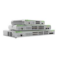
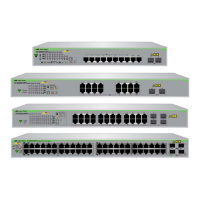
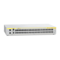
Figure 1 illustrates the front panels of the AT-GS908M, AT-GS916M, and
AT-GS924M Gigabit Ethernet Switches.
Figure 1. AT-GS908M, AT-GS916M, and AT-GS924M Front Panels
AT-GS924M
AT-GS916M
10/100/1000Base-T
Twisted-Pair Ports
AT-GS908M
Reset Button
Port LEDs
SFP LED
Console Port
Status LEDs
Mode
Button
Mode
LEDs
SFP Slot
10/100/1000Base-T
Twisted-Pair Ports
Reset Button
Port LEDs
SFP LEDs
Console Port
Status LEDs
Mode
Button
Mode
LEDs
10/100/1000Base-T
Twisted-Pair Ports
Reset Button
Port LEDs
SFP LEDs
Console Port
Status LEDs
Mode
Button
Mode
LEDs
SFP Slots
SFP Slots

Table of Contents

Other manuals for Allied Telesis AT-GS900M Series

Questions and Answers:

Question and Answer IconNeed help?

Do you have a question about the Allied Telesis AT-GS900M Series and is the answer not in the manual?

Allied Telesis AT-GS900M Series Specifications

General IconGeneral
BrandAllied Telesis
ModelAT-GS900M Series
CategorySwitch
LanguageEnglish

Related product manuals