Chapter 1: Overview
24
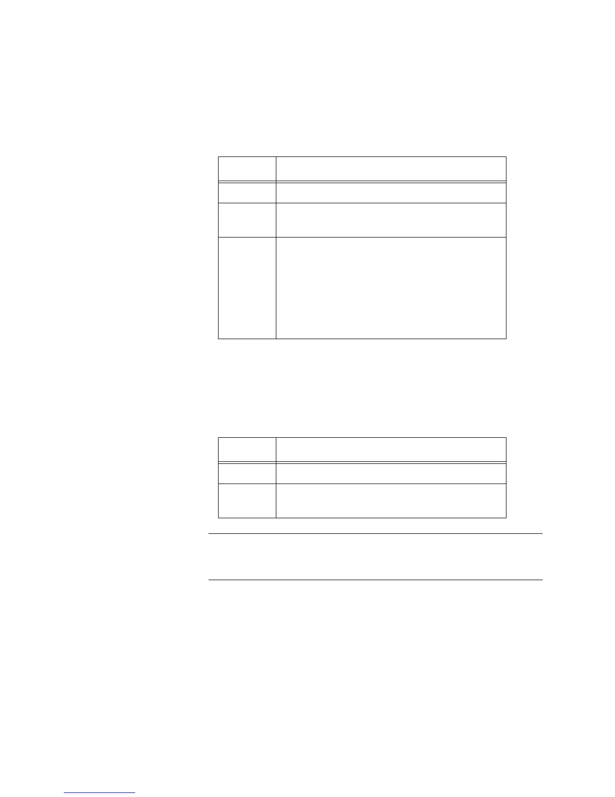
FAULT LED
The FAULT LED reports any conditions on the switch that are not normal.
Table 3 describes the states of the FAULT LED.
STANDBY LED
The STANDBY LED indicates whether the power is in a standby state.
Table 4 describes the states of the STANDBY LED.
The management web interface or CLI is used to set the Standby
state.
MODE LEDs The MODE LEDs display which mode is selected on the switch: Speed or
Duplex. The mode is selected using the Mode button, located on the left
side of the front panel of the switch. For a description of the Mode button,
refer to “Mode Button” on page 29.
The MODE LEDs are located on the left side of the front panel of the
switch. See Figure 4 on page 25.
Table 3. FAULT LED Functional Description
State Description
Off Normal switch operation.
Steady
Red
Abnormal system operation.
Flashing
Red
One of following:
Firmware downloading and being
written to flash memory.
DC internal power operating outside
the normal range.
Temperature out of range.
Table 4. STANDBY LED Functional Description
State Description
Off Power not in standby state.
Steady
Green
Power in standby state.

 Loading...