Chapter 5 Detailed Function Introductions
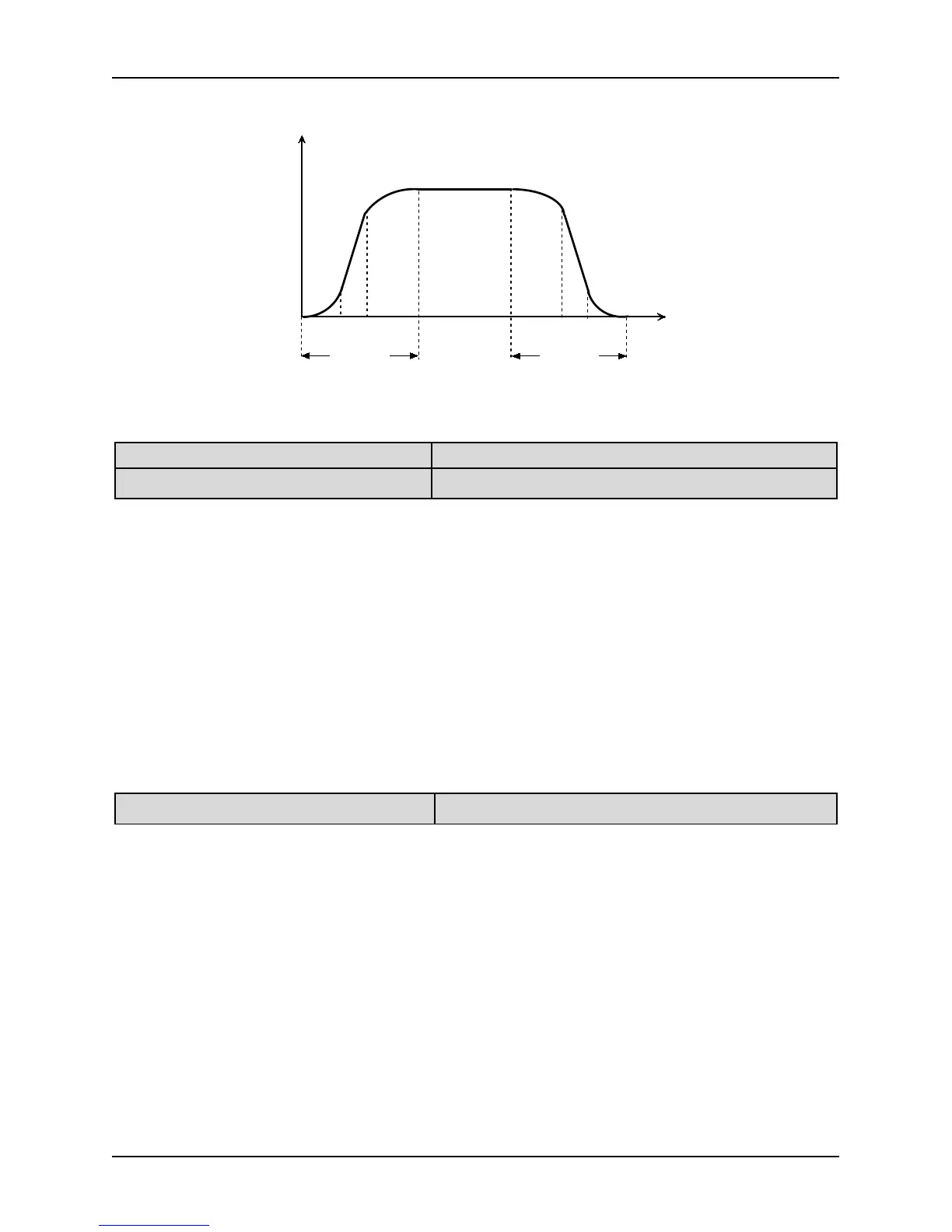
Running Freq.(Hz)
Time
Acc Time
Dec Time
③
②
①
①
③
②
Figure.5-1-6 S-curve acceleration/deceleration
P1.08 Time of S-curve initial Setting range: 10.0~50.0% [20.0%]
P1.09 Time of S-curve rising Setting range: 10.0~80.0% [60.0%]
Notes:
P1.08 and P1.09 are only active when the Acc/Dec mode is S-curve mode (P1.07=1) and P1.08+P1.09≤90%.
Starting process of S-curve is shown in Figure. 5-1-6 as “①”, where the changing rate of output frequency
Rising process of S-curve is shown in Figure. 5-1-6 as “②”, where the changing rate of output frequency is
Ending process of S-curve is shown in Figure. 5-1-6 as “③”, where the changing rate of output frequency
S-curve Acc/Dec mode is suitable for the conveying load such as elevator and conveying belt.
P1.10 Stop mode Setting range: 0~2 [0]
0: Deceleration to stop 1: Coast to stop
2: Deceleration +DC braking
Notes:
After receiving the stop command, the inverter reduces its output frequency within the Dec time, and stops
when the frequency decreases to zero.
After receiving the stop command, the inverter stops output immediately and the load stops under the effects
of mechanical inertia.
2: Dec-to-stop +DC braking
After receiving the stop command, the inverter reduces its output frequency according to the Dec time and
starts DC braking when its output frequency reaches the preset frequency of braking. Refer to the Notes of
P1.11~P1.15 for the functions of DC braking.
 Loading...

