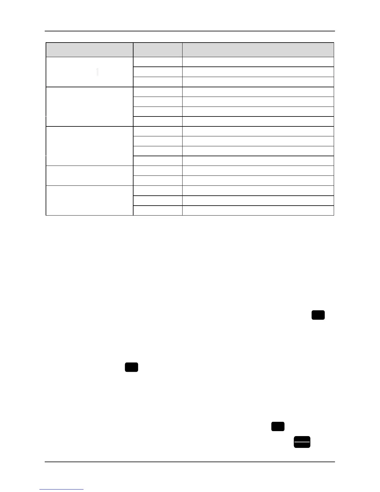
Table 3-3 Description of state indicators
Indicator Display state The current state of the inverter indicated
RUN Running-state LCDs
Off Stop
On Running
Flicker Zero frequency operation
FWD Forward running direction
indication
Off Reverse rotation or not run
Normally on Stable positive rotation
Quick flash Acceleration and deceleration of positive rotation
Slow flash Stop, the direction is forward
REV Reverse running direction
indication
Off Positive rotation or not run
Normally on Stable reverse rotation
Quick flash Acceleration and deceleration of reverse rotation
Slow flash Stop, reverse direction
TRIP failure indicator
Off Normal
Flicker Failure
REMOTE indicator
(Exclusive for control keypad)
Off Keypad control state
On Terminal control state
Flicker Serial communication state
3.1.4 Display state of keypad
The working state of this series inverter includes two states: stop state and running state.
Stop State: If there is no running command input after the inverter is power on and initialized, or the inverter has
received a stop command input, the inverter will come into stop state.
Running state: The inverter has received a running command and then comes into running state.
Therefore, the display states of keypad include display of stop state, display of running state and display of
programming state and display of fault and warning state.
Display of stop state
If the inverter is a stop state, the four digitals of keypad will display the parameters value of stop state: For example,
the output frequency. See Figure-3-2, and the unit indicator will indicate the unit of the parameter. Press
key,
the keypad will cycling display the value of different monitoring objects (selected by the parameter group PC) .
Display of running state
If the inverter got an effective running command, it will come into running state. Then the four digitals of keypad
will display the parameters value of running state. See example of Figure 3-3-3. and the unit indicator will indicate
the unit of the parameter. Press
key, the keypad will cycling display the value of different monitoring objects
(selected by the parameter group PC) .
Fault and warning state
If the inverter has checked out a warning signal, it will come into warning state and show the warning code
flickeringly. See example of Figure 3-3-5. If the warning signal disappeared, the warning code will automatically
disappear. If the inverter has checked out an error, it will come into fault state and show the fault code steadily.
Moreover, the indicator TRIP will light up, see example of Figure 3-3-6. By pressing the