Chapter 4 Parameter Index
Notes:
“○”means that the parameters can be changed during inverter running and stop state;
“×”means that the parameters cannot be changed during running;
“*” means that the actually measured value or fixed parameters cannot be changed;
“-” means that the parameters can be only set by the manufacturer and cannot be changed by the user.
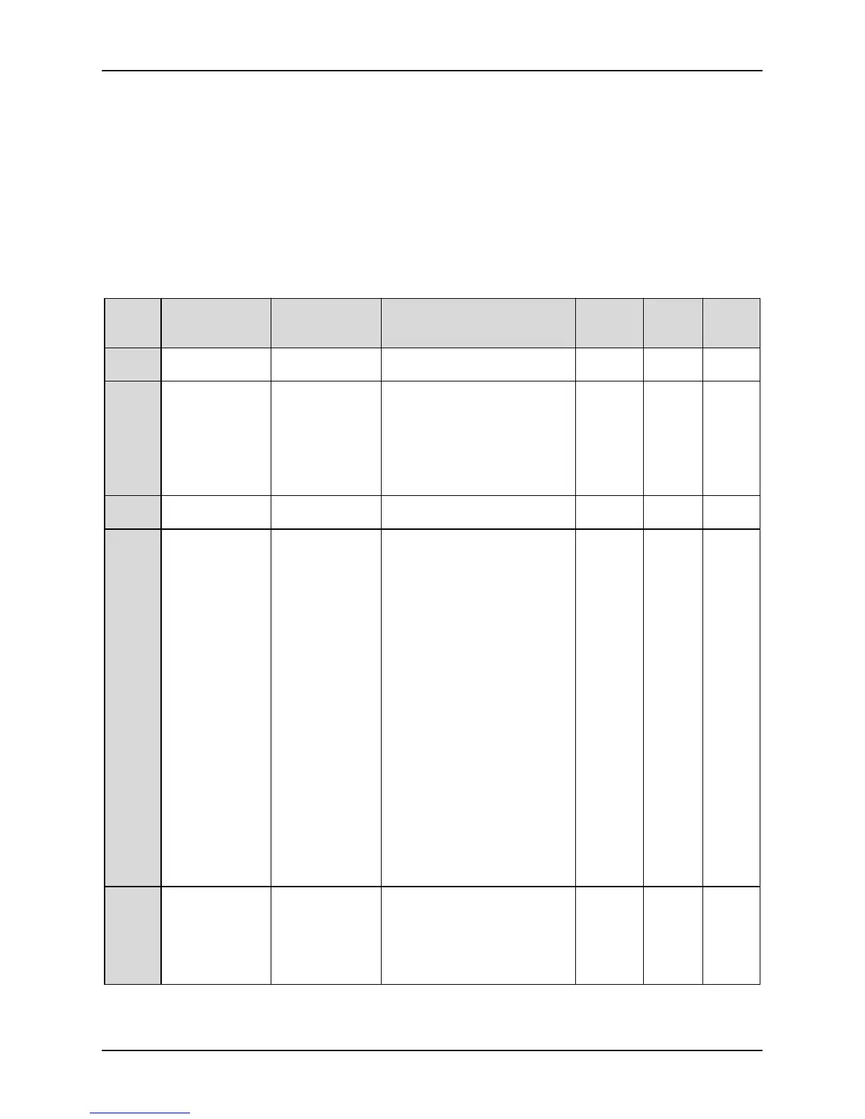
P0: Basic function
Functi
on code
Parameter LCD display Setting range
Factory
setting
Mod.
MODB
US
address
P0.00
Menu display
mode
Menu display
mode
0: Standard menu
1: Check mode menu
0 ○ 0100
P0.01 Control mode Control mode
0: V/F control
1: Closed-loop vector control
2: Open-loop vector control
3: V/F separation control
(Closed loop vector control
mode is only active for
ALPHA6000V series inverters)
2 × 0101
P0.02
Frequency digital
setting
Frequency digital
setting
0-maximum frequency 0.00Hz ○ 0102
P0.03
Frequency
setting source 1
Frequency
setting source 1
0: NULL
1: Frequency digital setting,
digital knob adjustment
2: Terminal AI1
3: Terminal AI2
4: Terminal AI3 (reserve for
3004GB and below
models)
5: Pulse input
6: Communication setting
7: Line speed (reserve)
8: Multi-stage speed
9: Terminal UP / DOWN
10: Program timing run (PLC)
11: PID
12: Wobble frequency run
(reserve)
When the frequency source is 0
~ 7, if multi-stage speed
terminals are effective, operate
according to the operation
process of "multi-stage speed"
1 × 0103
P0.04
Frequency
setting source 2
Frequency
setting source 2
0-8 (consistent with P0.03)
9: Torque difference
compensation dosage
This frequency source has no
multi-stage speed terminal
priority mechanism
0 × 0104