Chapter 6 Troubleshooting
6.2 Warning display and explanation
After action of warning function, warning code is flickered display, but the inverter is not in fault-protecting state:
PWM output will not be closed off, fault relay will not act. In addition, the inverter would automatically return to
prevenient operation state after the warning signal disappeared.
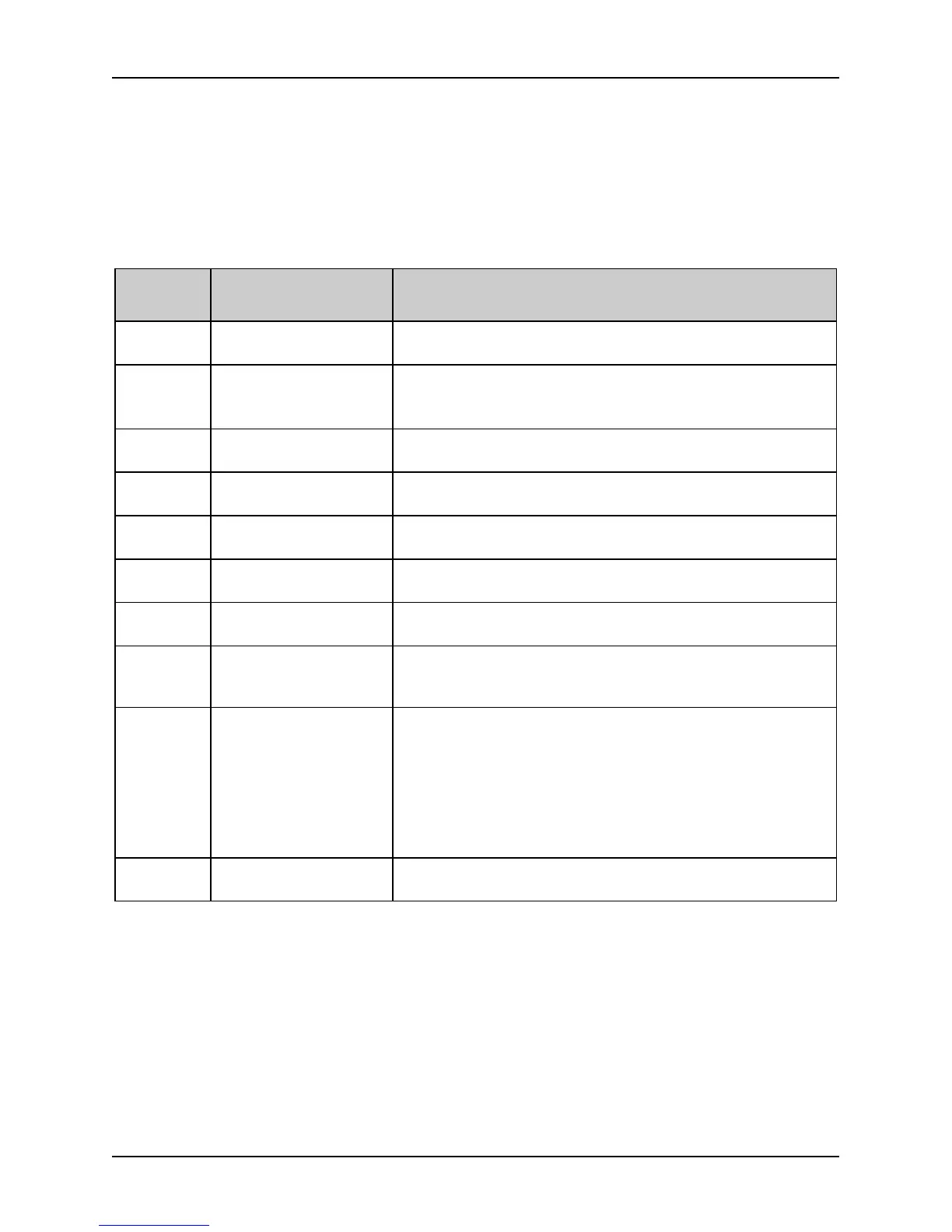
The following table lists different kinds of Warnings.
Table 6-2 Warning display and description
Alarm
Display
Display Content Description
Uu Undervoltage detection
Undervoltage is detected. The frequency inverter can still work in
this case.
OLP2
Frequency inverter
overload pre-alarm
The frequency inverter working current is over the overload
detection level and the duration is over the overload detection time.
In this case, the frequency inverter can still work.
OH2 Heat radiator too high
The heat radiator temperature is larger than the OH2 detection
benchmark. In this case, the inverter can still work.
AE1
Analog signal 1 is
abnormal
The input analog signal in the analog input signal passage AI1
exceeds the allowed maximum range of -0.2~+10.2V.
AE2
Analog signal 2 is
abnormal
The input analog signal in the analog input signal passage AI2
exceeds the allowed maximum range of -0.2~+10.2V.
AE3
Analog signal 3 is
abnormal
The input analog signal in the analog input signal passage AI3
exceeds the allowed maximum range of -0.2~+10.2V.
SF1
Function code setting is
inappropriate
For example, for the I/O terminal, SS0-2 and TT0-1setting is not
incomplete
The manner selection is
inconsistent with the
terminal setting
The operation manner set is inconsistent with the setting of terminal
X1~X10.
SF3
Wrong output terminals
are selected (only for
inverters of 35R5GB and
the above)
There are totally three open collector output circuits with the
frequency inverter. The output terminals D0, Y1, Y2 and Y3are
programmable multifunctional terminals. The user can output some
control and monitoring signals selectively based on the need. When
the collector output is selected as the program operation step
indication or fault indication, the function-defined content should
be the same, all 26 or 27, to make the combination of D0, Y1, Y2
and Y3 effective.
Parameter setting is
abnormal
The parameter setting is abnormal. The inverter will escape from
the parameter setting automatically.
6.3 Motor’s faults and corrective measure
If the motor has one of the following faults, please find the reason and take corresponding corrective measure. Seek
for tech support if the measure does not work
 Loading...

