5.10 V/F Control (Group P9)
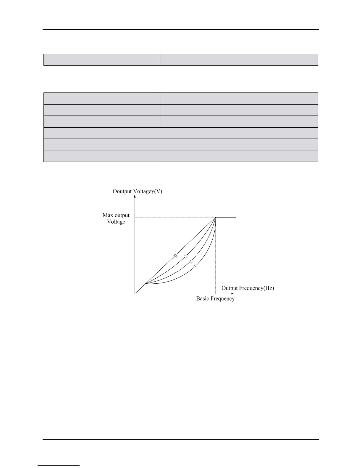
P9.00 V/F curves setting Setting range: 0~4 [0]
0: Constant Torque Characteristic Curve 0 1: Reduction Torque Characteristic Curve 1 (2.0)
2: Reduction Torque Characteristic Curve 2
(1.5)
3: Reduction Torque Characteristic Curve 1 3 (1.2)
P9.01 V/F frequency value F1 Setting range: 0.0~P9.03 [10.00Hz]
P9.02 V/F voltage value V1 Setting range: 0~100.0% [20.0%]
P9.03V/F frequency value F2 Setting range: P9.01~P9.05 [25.00Hz]
P9.04 V/F voltage value V2 Setting range: 0~100.0% [50.0%]
P9.05 V/F frequency value F3 Setting range: P9.03~P0.09 [40.00Hz]
P9.06 V/F voltage value V3 Setting range: 0~100.0% [80.0%]
Notes:
Figure 5-9-2, the V/F curve is defined with the four-point broken line to be adapted for the special load
characteristics. Notes: V1<V2<V3. In the case of low frequency, if the voltage is set to be too high, the
motor may be overheated and even burned, and the frequency inverter may stall over current or be
over-current protected.