1, Only turn on the input power supply after replacing the front cover. Do not
remove the cover while the inverter is powered up.
2, When the retry function is selected, do not approach the inverter or the load, since
it may restart suddenly after being stopped.
1, Since the stop key can be disabled by a function setting, install a separate
emergency stop switch.
2, Since it is very easy to change operation speed from low to high speed, verify the
safe working range of the motor and machine before operation.
3, Do not check signals during operation.
4, All inverter parameters have been preset at the factory. Do not change the settings
unless it is required. Failure to observe these precautions may result in equipment
damage, serious personal injury or death.
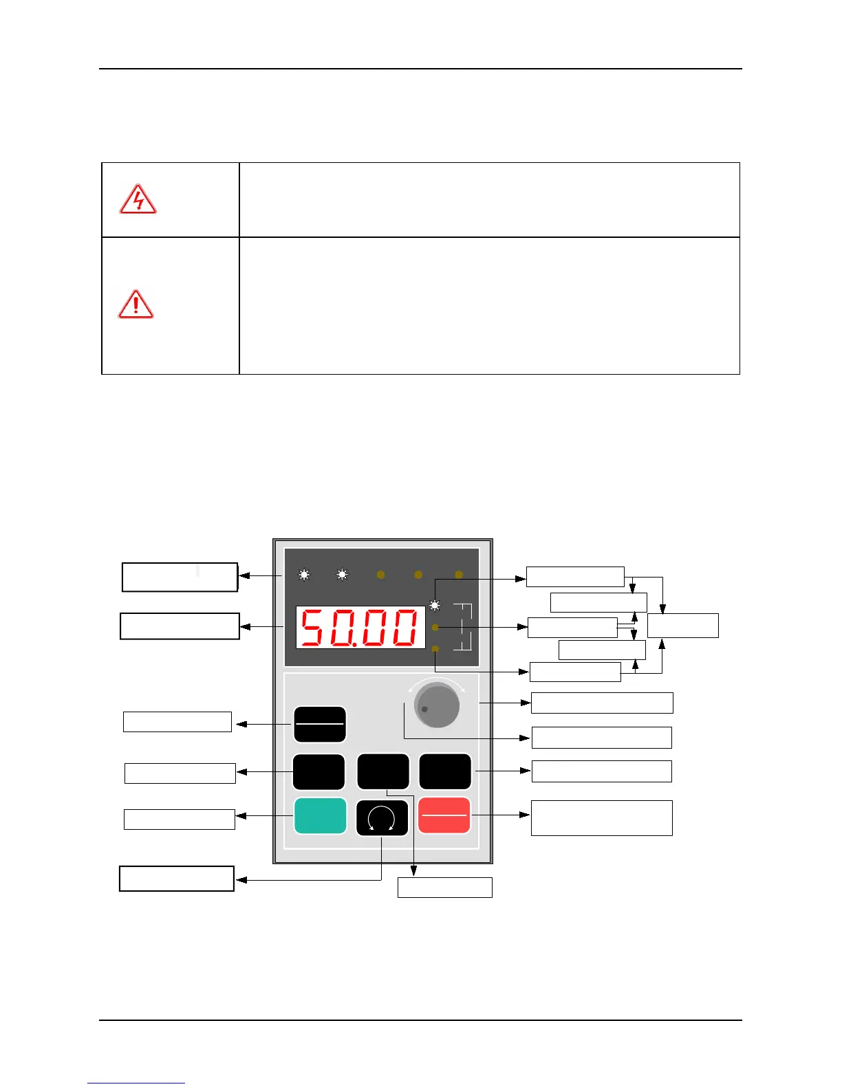
3.1 Function and operation of keypad
The keypads of the inverter may have different exterior dimensions. However, all of them have the same array of
buttons and LED display. Moreover, operation and function of them are all the same. Every keypad has four digitals
seven segments LED monitor, nine operation buttons, a digital encoder, and eight led indicators (five for status
indication and three for unit indication). User can perform function setting, inverter running, stop, and status
monitoring with the keypad.
3.1.1 Keypad layout
Fig. 3-1 Keypad layout and name of each part
Above the keypad are five status indicators: RUN, FWD, REV, REMOTE and TRIP. The indicator RUN will be lit
up if the inverter is running; the indicator FWD will be lit up if it running forward and the indicator REV will be lit
up if it runs reverse. The indicator REMOTE will be lit up if the inverter is not controlled by keypad. The indictor
TRIP will be lit up if fault occurs. To see the details, see Chapter 3-3 description.