In monitoring status, the LED will display the content of current monitoring object. At abnormal state It will display
the fault code when the inverter falls to run and show the warn code when the inverter is warning. At normal state, it
will display the object selected by parameter group PC. See table 3-1 description for details.
In programming mode, nixie tube displays three-level menus: function group, function codes and function parameter
values. Under the function group display menu, it displays function group from "-P0-" to "-PF-"; under function
code menu, it displays the corresponding function codes in the group. Under the parameters displayed in the function
menu, the parameter values will be displayed.
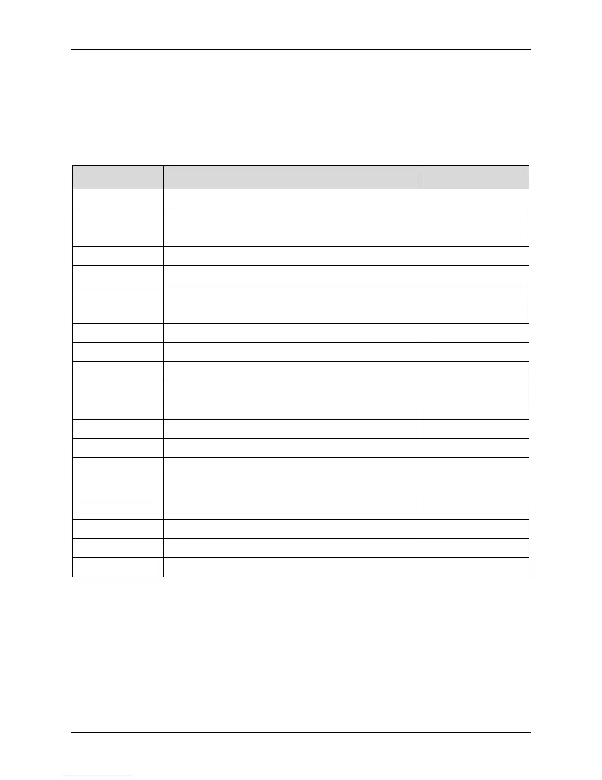
Table 3-1 The LED monitoring objects
PC display control Monitoring object
Permission of Modify
in running state
PC.01=1 Output frequency (Hz) (before compensation)
PC.02=1 Output frequency (Hz) (actual)
PC.03=1 Output current (A)
PC.04=1 Setting frequency (Hz blink) permission
PC.05=1 Motor rotate speed (r/min)
PC.06=1 Setting speed (r/min blink) permission
PC.07=1 Running linear speed (m/s)
PC.08=1 Setting linear speed (m/s blink)
PC.09=1 Output power (no unit)
PC.10=1 Output torque (%)
PC.11=1 Output voltage (V)
PC.12=1 Bus voltage (V)
PC.13=1 AI1 (V)
PC.14=1 AI2 (V)
PC.15=1 AI3 (V) (reserve for 3004GB and below models)
PC.16=1
Analog PID feedback (all unit lights are normally open, no
unit)
PC.17=1 Analog PID setting (all unit lights flicker, no unit) permission
PC.18=1 Extern count value (no unit)
PC.19=1 State of terminal (no unit)
PC.20=1 Actual length(m)
3.1.2 Description of button function
On the inverter keypad, there are nine buttons. In addition, the function of each button is defined as table 3-2.