Chapter 5 Detailed Function Introductions
Figure. 5-9-2 V/F-curve defined by user
P9.07Torque boost mode Setting range: 0.0~30.0% [0.0%]
Notes:
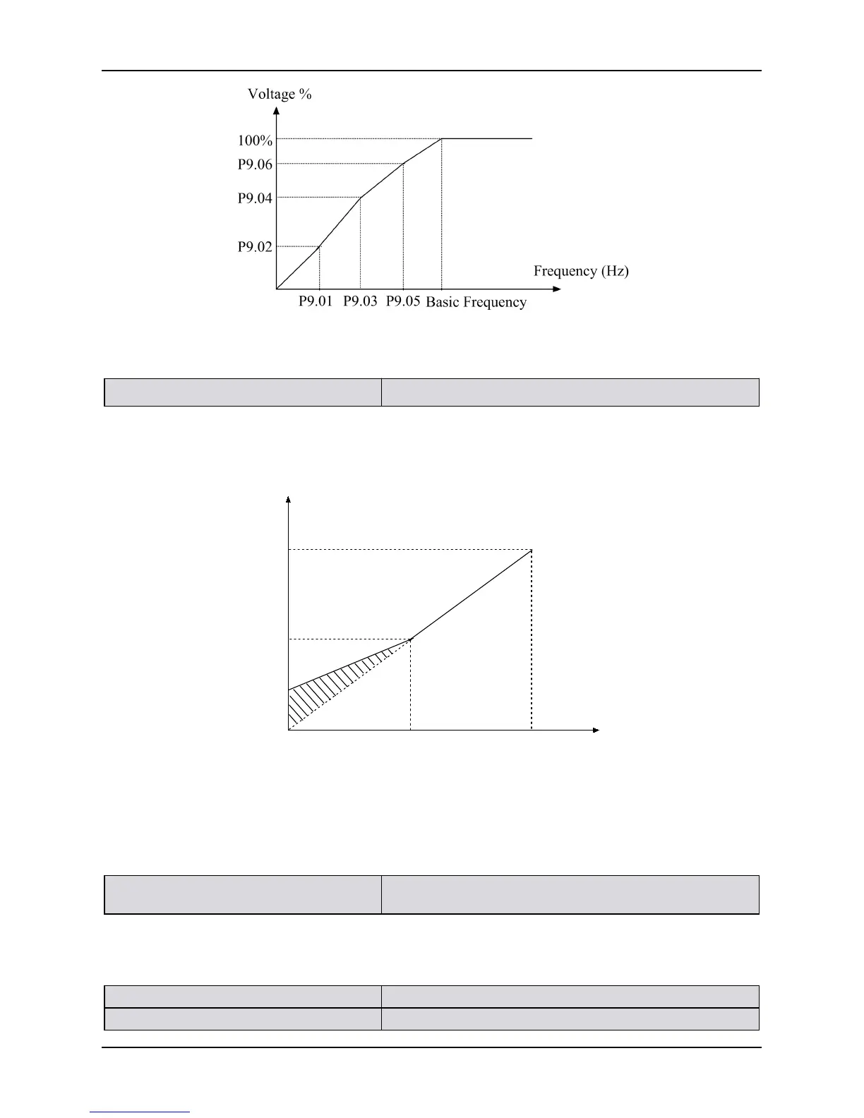
To make up for the low-frequency torque characteristic, certain boost compensation can be made for the
output voltage. When the function code is set as 0.0%, it is at the V/F control mode; when it is not set as 0,
it is at the manual torque boost mode, as showed in Figure 5-9-3.
Output voltage
Output Freq.
Basic operation frequencyCut-off Freq. for torque boost
Manual
torque boost
Max output
voltage
Figure 5-9-3 Manual Torque Boost
1. Wrong parameter setting can cause overheat or over-current protection of the motor.
2. When the inverter drives synchronous motor, torque boost function is recommended to be used and V/F curve
should be adjusted according to the motor parameters.
P9.08 Cut-off point used for manual torque
boost
Setting range: 0.00~50.00Hz [16.67 Hz]
Notes:
This function defines the cutoff frequency for manual torque boost as showed in Figure 5-9-3. The cutoff
frequency is applicable to any V/F curve determined by P9.00.
P9.09 Gain of slip frequency compensation Setting range: 0.0~250.0% [0.0%]
P9.10 Slip compensation time const Setting range: 0.01~2.55S [0.20S]