Chapter 5 Detailed Function Introductions
%
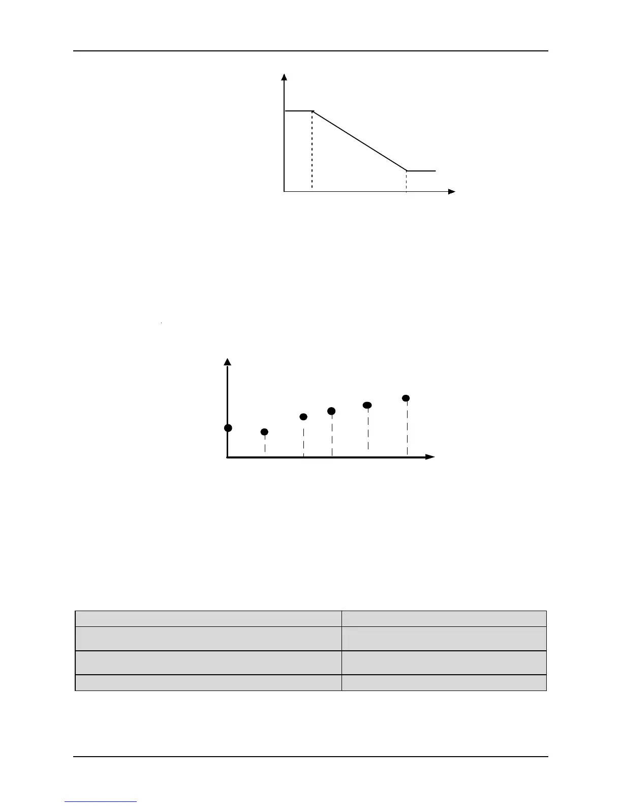
Min analog
value (V)
Max analog
value (V)
Phys ical value
corres ponding to Min
analog value Input%
Phys ical value
corres ponding to Max
analog value Input%
Figure. 5-4-1 Analog input linear curve
Note 2:
When P4.00 is set to 1, 2, or 3, the function of P4.01~P4.04, P4.06~P4.09 and P4.11~P4.14 are combined for
one physical value, which is different to Note 1. User can define their own nonlinear curves by setting these
parameters. Six points can be set on the curve. As shown in Figure. 5-4-2. In addition, the setting value to
P4.01, P4.03, P4.06, P4.08, P4.11, P4.13 must increase in order.
P hysical value corresponding t o
analog value Input %
P4.08P4.03
P4.13
P4.01
P4.11P4.06
Analog
input
P4.02
P4.04
P4.07
P4.09
P4.14
P4.12
Figure. 5-4-2 Analog input non-linear curve
Note 3:
The input filter time constant is used for digital filter of the input signal, in order to avoid interference of the
The bigger the filter time constant, the higher the immunity level and the longer the response time is. On the
contrary, the smaller the time constant, the shorter the response time and the lower the immunity level is. If
the best setting is not clear, you can adjust setting value according to the status of control stability and
response delay time.
P4.21 AO1 function definition Setting range: 0~14 [0]
P4.22 AO2 function definition
(reserve for 3004GB and below models)
Setting range: 0~14 [0]
P4.23 AO3 function definition
(reserve for 3004GB and below models)
Setting range: 0~14 [0]
P4.24 DO function definition Setting range: 0~14 [0]
0: NULL 1: Output current (0-2IN)
2: Output voltage (0 (0 ~ 10V / 0 ~ 20mA) maximum
voltage)
3: PID setting (0 ~ 10V)
4: PID feedback (0 ~ 10V) 5: Calibration signal (5V )