Appendix 4 Use of MODBUS Communication
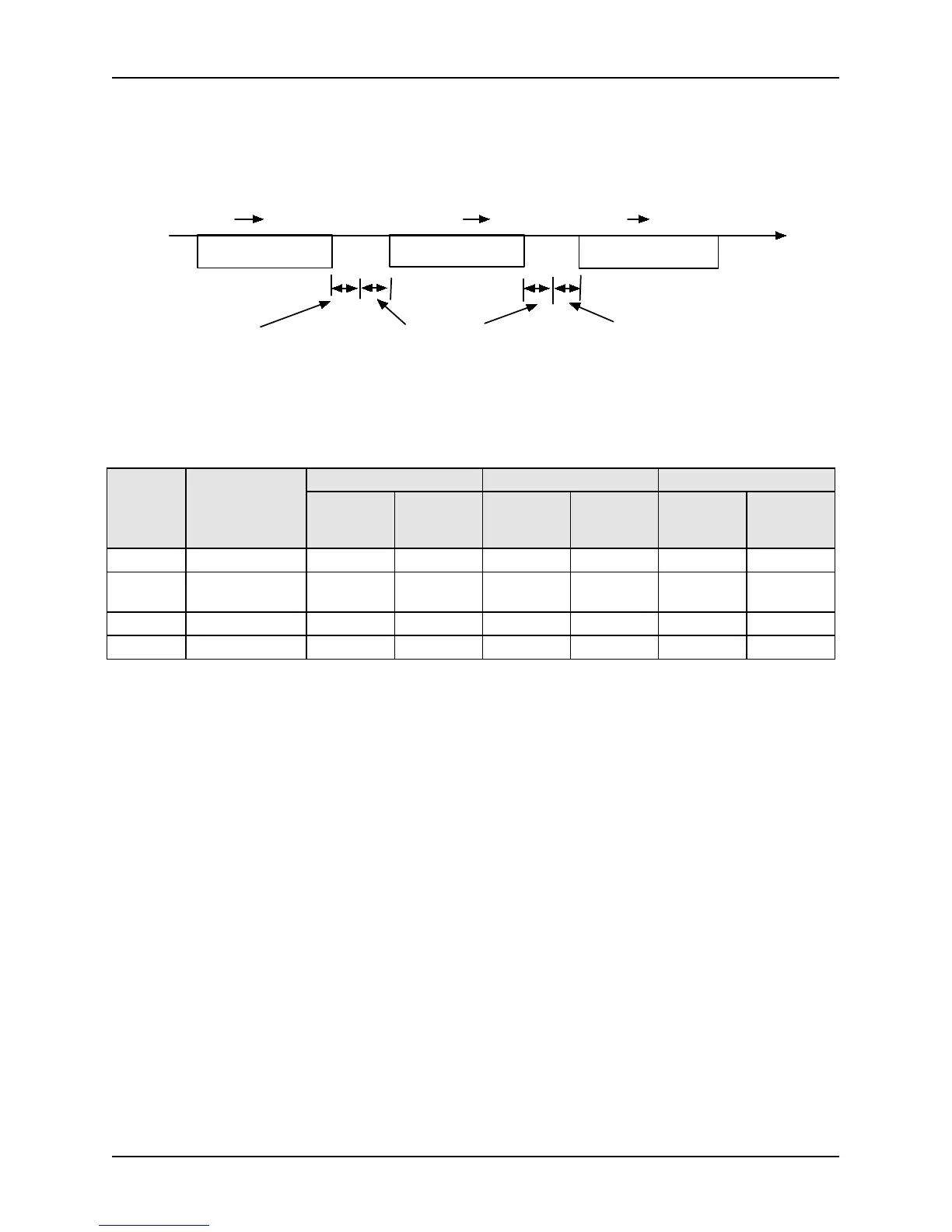
During communication, the main controller (PLC, etc) gives commands to ALPHA6000S/ALPHA6000V,
and the frequency inverters respond to them. The process constitutes the information transmission &
receiving as showed in the right figure. As the command function content varies, the length of data will vary
as well. The interval between two commands should maintain the time recorded below.
PLC 变频器 PLC变频器 变频器
t(ms)
3.5char Pb.04设定
3.5char
5ms以上
指令
响应
指令
PLC
Frequency inverter address: Frequency inverter address (0 ~ 31)
When it is set as 0, commands are transmitted together with the broadcast manner. Even if the broadcast command is
received, the frequency inverter will not give response.
There are four types of MODBUS command codes supported by the series of frequency inverters, which are
showed as follows:
Command
Code
(16 bits )
Function
Command Length Normal Response Length Abnormal Response Length
Minimum
Byte
Number
Maximum
Byte
Number
Minimum
Byte
Number
Maximum
Byte
Number
Minimum
Byte
Number
Maximum
Byte
Number
03H Reading Record 8 8 7 7 5 5
06H
Single Character
Writing
8 8 8 8 5 5
08H Loopback Test 8 8 8 8 5 5
10H Writing Record 11 11 8 8 5 5
The calculation method for CRC-16 used by MODBUS communication is as follows:
1. Generally, when CRC-16 is calculated, its initial value is 0, and the initial value of the communication terminal
series is set as 1. (1 for 16 bits)
2. LSB according to the frequency inverter address is MSB, and the final data MSB uses LSB to calculate CRC-16.
3. The response command of frequency inverter also has to calculate CRC-16 to be compared with CRC-16 in the
response command.
Unsigned int CRC16(unsigned char*uptr, unsigned int ulenth)
{
unsigned int crc=0xffff ;
unsigned char uindex ;
if(ulenth>=9)
{
ulenth=9;
}
while(ulenth!=0)
{
crc^=*uptr ;
for(uindex=0;uindex<8;uindex++)
{
if((crc&0x0001)==0)
{
crc=crc>>1 ;
 Loading...

