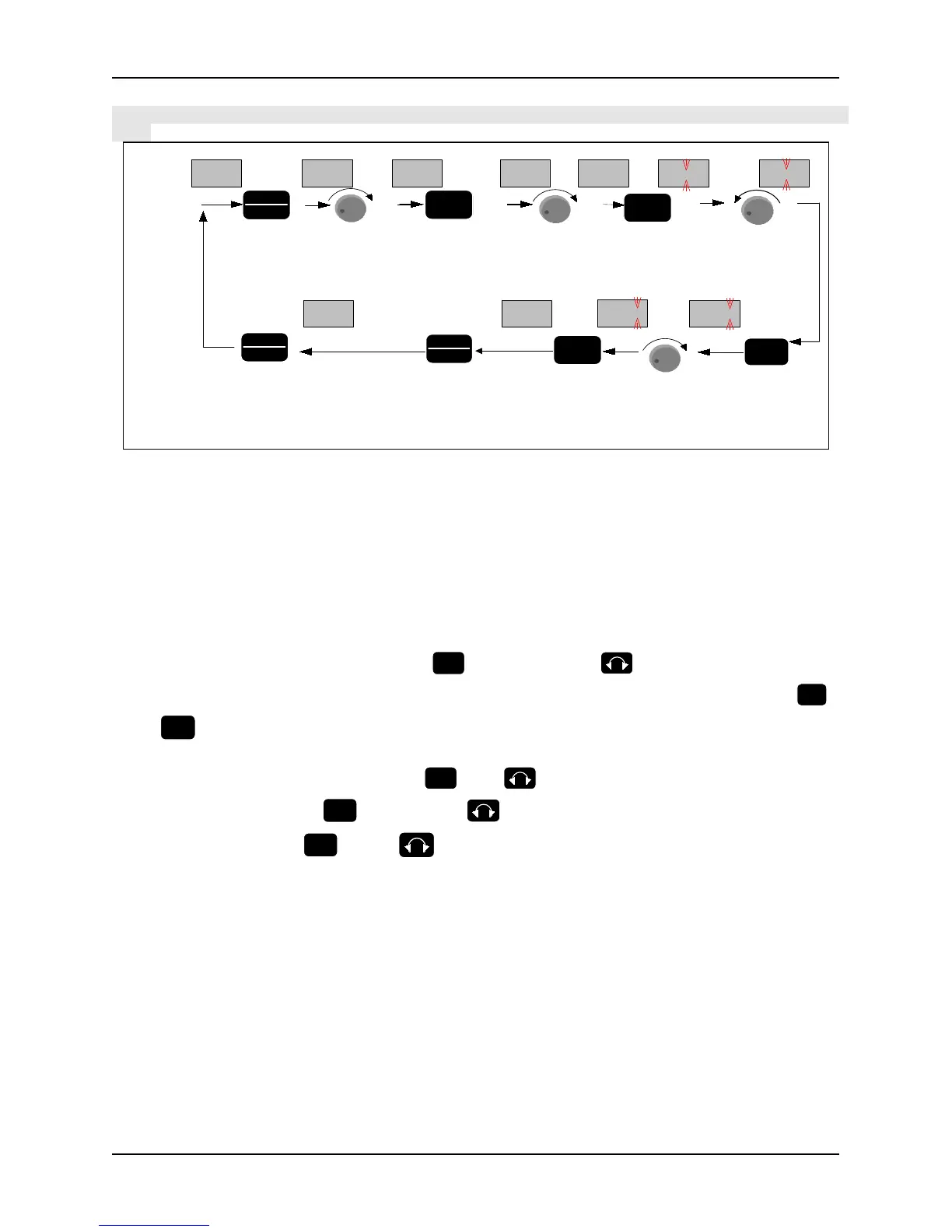
Setting of function code parameters: (example of changing Jog acceleration time, function code P2.01 from 6.0s to
3.2s)
0.00
P 2.01
monitoring
state
go into
programming
state.display
parameter
group menu
Enter
into
parameter
code
number
menu
turn right 1
time,chose
parameter
code
number
P 2.01
Enter into
parameter
value menu
Turn left 3
times to
chang the
number to 3
save the
changed value
and exit to
parameter
code number
menu
Display
of LED
Operation
of key
Shift to
change the
blinking
place to
right
Exit to
parameter
group
menu
Turn right 2
times to
change the
number to 2
Exit from
the
programming
state
turn right 2
times,chose
parameter
group
P 2
P 2.00
-P 2--P 0-
-P 2-
P 2.02
003.2 003.0
006.0 003.0
E NT E R
P R G
E S C
E N T E R
> >
P R G
E S C
P R G
E S C
E N TE R
E N TE R
+
+
+
-
Figure 3-7 Flow chart of parameter setting
In three-level menu state, no flicker bit for a parameter indicates that the function code cannot be modified, and the
possible reasons include:
Modifying the value is forbidden because the parameter is actual measure value, or running record value or
fixed value. The function parameter cannot be changed when the inverter is at running state. However, it can
be changed at stop state.
So stop the inverter and then change the parameter value.
The inverter parameters are protected. If function parameter value PF.01=1 or 2, the parameters are forbidden
to be changed. This parameter protection function is to avoid operation mistake. To change the protection
parameters, change value of function code PF.01 to zero, then all the parameters can be changed
Note: When the digital encoder is damaged,
UP/DN activation method: UP/DN function can be activated by pressing the key combination
for 5s (operation illustration is shown in Fig3.8), which will reset after powering off. Parameter
PD.12 can be set by activating UP/DN function, please see PD.12 function description for details
In monitoring or alarm mode: function of
acts as DN. continuous augmentation function is
for 2s (operation illustration is shown in Fig. 3-9: modify the
run command control mode setting P0.07 = 0: keypad control into 4: serial communication)