1 Other defects — If the problem persists after checking "[7] LAN",
replace MAIN Assy.
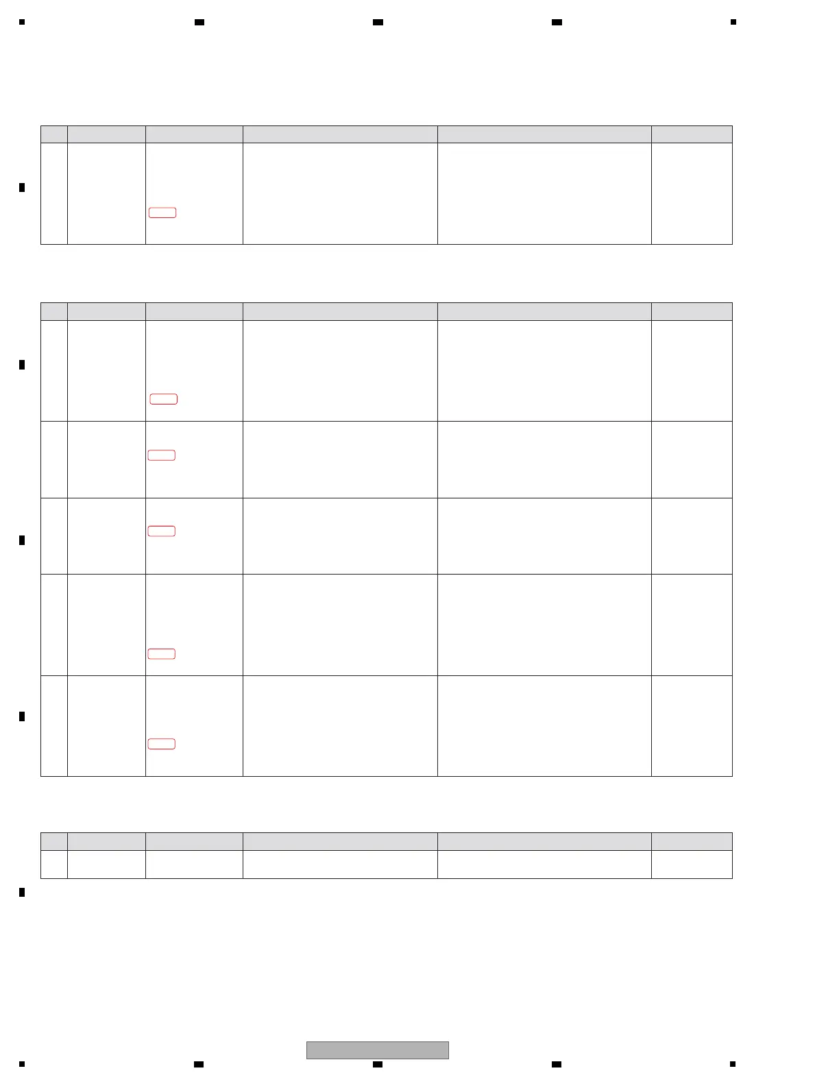
[2-1-9] "E-0100" is displayed
LAN Reset error was generated.
Step Cause Diagnostics Point Item to be Checked Corrective Action Reference
2-1-7-1
—Check the following voltages at the
diagnostics point.
[The communication between MAIN CPU/DSP
and Authentication Coprocessor]
IC1504
RST (0 V)
SCL (3.3 V amplitude)
SDA (3.3 V amplitude)
1 Communication
error between
MAIN CPU/DSP
and
Authentication
Coprocessor
MAIN Assy
IC1504
7 pin (RST)
6 pin (SCL)
2 pin (SDA)
!
If an output signal can be confirmed, replace
MAIN Assy.
! If not, the circuit or the parts between IC1101
and IC1504 may be defective.
If the parts other than IC1101 and IC1504 are
defective, replace its. If IC1101 or IC1504 is
defective, replace MAIN Assy.
[2-1-7] "E-0040" is displayed
A communication error of Authentication Coprocessor (MFi IC) was generated.
Step Cause Diagnostics Point Item to be Checked Corrective Action Reference
2-1-8-1
—1 Power defect of
USB/ETHER UCOM
(IC401)
MAIN Assy
TP V+3R8D
TP VRTC
TP VDD1
TP VIO
TP VAUX2
! If the voltage of the all points are confirmed
correctly, go to step 2.
! If not, the circuit or the parts between IC402
and IC401 may be defective.
If the parts other than IC401 are defective,
replace its. If IC401 is defective, replace
MAIN Assy.
[2-1-8] "E-0080" is displayed
A communication error between MAIN CPU/DSP and USB/ETHER UCOM (Parameter side) was generated.
Step Cause Diagnostics Point Item to be Checked Corrective Action Reference
Check the following voltages at the
diagnostics point.
[The power of USB/ETHER UCOM]
V+3R8D (3.8 V)
VRTC (1.83 V)
VDD1 (1.325 V)
VIO (1.5 V)
VAUX2 (3.3 V)
2-1-8-2
—2 The parts defect
or the mount
defect on RST
line of
USB/ETHER UCOM
(IC401)
MAIN Assy
TP AM_XRST
!
If the voltage is confirmed correctly, go to step 3.
! If not, the circuit or the parts between IC402,
IC803, IC802 and IC401 may be defective.
If the parts other than IC401 are defective,
replace its. If IC401 is defective, replace
MAIN Assy.
Check the following voltages at the
diagnostics point.
[RST of USB/ETHER UCOM]
AM_XRST (3.3 V)
2-1-8-3
—3 The parts defect
or the mount
defect on CLK
line of
USB/ETHER UCOM
(IC401)
MAIN Assy
R801 (AM_PLL_24M)
!
If the voltage is confirmed correctly, go to step 4.
! If not, the circuit or the parts between X801
and IC401 may be defective.
If the parts other than IC401 are defective,
replace its. If IC401 is defective, replace
MAIN Assy.
Check the following voltages at the
diagnostics point.
[CLK of USB/ETHER UCOM]
AM_PLL_24M (1.8 V 24 MHz)
Refer to "[7] LAN".
2-1-8-4
—4
SPI communication
error between
USB/ETHER UCOM
(IC401) and
FLASH ROM (16Mb)
(IC806)
MAIN Assy
IC806
1 pin (AM_FLASH_XCS)
2 pin (AM_FLASH_MISO)
5 pin (AM_FLASH_MOSI)
6 pin (AM_FLASH_SCK)
!
If an output signal can be confirmed, go to step 5.
! If not, the circuit or the parts between IC401
and IC806 may be defective.
If the parts other than IC401 are defective,
replace its. If IC401 is defective, replace
MAIN Assy.
Check the following voltages at the
diagnostics point.
[SPI communication of FLASH ROM(16Mb)]
IC806
AM_FLASH_XCS
(3.3 V d 0 V)
AM_FLASH_MISO
(3.3 V amplitude)
AM_FLASH_MOSI
(3.3 V amplitude)
AM_FLASH_SCK
(3.3 V amplitude)
2-1-8-5
—5 Communication
error between
MAIN CPU/DSP
(IC1101) and
USB/ETHER UCOM
(IC401)
MAIN Assy
R872 (AM_66AK_SCK1)
R873 (AM_66AK_MISO1)
R874 (AM_66AK_MOSI1)
R840 (AM_66AK_XCS1)
! If an output signal can be confirmed, replace
MAIN Assy.
! If not, the circuit or the parts between IC401
and IC1101 may be defective.
If the parts other than IC401 and IC1101 are
defective, replace its. If IC401or IC1101 is
defective, replace MAIN Assy.
Check the following voltages at the
diagnostics point.
[SPI communication between MAIN CPU/DSP
and USB/ETHER UCOM]
AM_66AK_SCK1
(3.3 V 9.6 MHz)
AM_66AK_MISO1
(3.3 V amplitude)
AM_66AK_MOSI1
(3.3 V amplitude)
AM_66AK_XCS1
(3.3 V amplitude)
[7] LAN
 Loading...