2-1-10-1
Check the following voltages at the
diagnostics point.
[Power supply of SUB DSP]
V+3R3D_SDSP
(3.3 V)
V+1R285D_SDSP
(1.285 V)
1 Power defect of
SUB DSP
MAIN Assy
TP
V+3R3D_SDSP
TP
V+1R285D_SDSP
! If the voltage is confirmed correctly, go to step 2.
! If the circuit of V+3R3D_SDSP is defective,
the error is able to detect at the voltage
monitoring circuit first. Refer to "5.4
INFORMATION ON POWER DIAGNOSTICS".
If the voltage of V+1R285D_SDSP is higher
than 1.285 V, it is able to detect at the voltage
monitoring circuit first. If lower than 1.285 V,
the circuit may have a short circuit. Confirm it,
and replace defective parts.
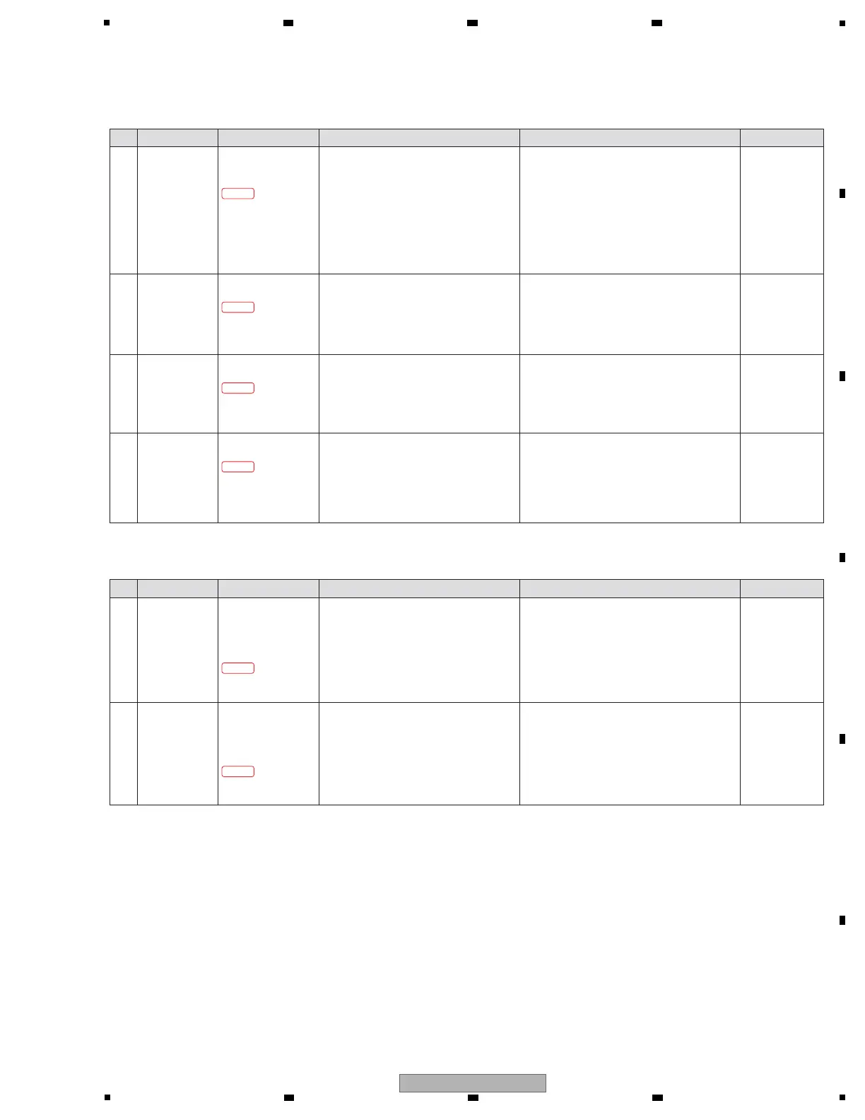
[2-1-10] "E-0200" is displayed
A startup error of SUB DSP (SRC) was generated.
Step Cause Diagnostics Point Item to be Checked Corrective Action Reference
5.4
INFORMATION
ON POWER
DIAGNOSTICS
2-1-10-2
Check the following voltages at the
diagnostics point.
[RST of SUB DSP]
SDSP_XRST (3.3 V)
2 RST defect of
SUB DSP
MAIN Assy
TP SDSP_XRST
! If the voltage is confirmed correctly, go to step 3.
! If not, the circuit or the parts between IC1101
and IC1901 may be defective.
If the parts other than IC1101 are defective,
replace its. If IC1101 is defective, replace
MAIN Assy.
—
2-1-10-4
Check the following voltages at the
diagnostics point.
[Release RST for IC2002]
CLKGEN_XOE (3.3 V)
4 RST defect of
IC2002
MAIN Assy
TP CLKGEN_XOE
! If the voltage is confirmed correctly, replace
MAIN Assy.
! If not, the circuit or the parts between IC1101,
Q3009 and IC2202 may be defective.
If the parts other than IC1101 are defective,
replace its. If IC1101 is defective, replace
MAIN Assy.
—
2-1-10-3
Check the following voltages at the
diagnostics point.
[CLK of SUB DSP]
SDSP_PLL24M (1.8 V 24 MHz)
3 CLK defect of
SUB DSP
MAIN Assy
TP SDSP_PLL24M
! If the voltage is confirmed correctly, go to step 4.
! If not, the circuit or the parts between X801,
IC801, IC1902 and IC1901 may be defective.
If the parts other than IC1901 are defective,
replace its. If IC1901 is defective, replace
MAIN Assy.
—
2-1-11-1
Check the following voltages at the
diagnostics point.
[SPI communication between
MAIN CPU/DSP and USB/ETHER UCOM]
AM_66AK_SCK (3.3 V
12 MHz d 9.6 MHz
)
AM_66AK_MISO (3.3 V amplitude)
AM_66AK_MOSI (3.3 V amplitude)
AM_66AK_XCS0 (3.3 V amplitude)
1
The communication
error between
MAIN CPU/DSP and
USB/ETHER UCOM
MAIN Assy
R845 (AM_66AK_SCK)
R870 (AM_66AK_MISO)
R846 (AM_66AK_MOSI)
R1618 (AM_66AK_XCS0)
!
If all output signals can be confirmed, go to step 2.
! If not, the circuit or the parts between IC401
and IC1101 may be defective.
If the parts other than IC401 and IC1101 are
defective, replace its. If IC1101 is defective,
refer to [2-1-2]. If IC401 is defective, refer
to [2-2-3].
[2-1-11] "E-0400" is displayed
A communication error between MAIN CPU/DSP and USB/ETHER UCOM (Link Cue side) was generated.
Step Cause Diagnostics Point Item to be Checked Corrective Action Reference
2-1-11-2
Check the following voltages at the
diagnostics point.
[Input CLK for MAIN CPU/DSP(DSP part)]
MDSP_BCK1-3 (3.3 V amplitude)
MDSP_LRCK1-3 (3.3 V amplitude)
2
Input CLK defect
of MAIN CPU/DSP
(DSP part)
MAIN Assy
R1846, R1825, R1826
(MDSP_BCK1-3)
R1855, R1836, R1837
(MDSP_LRCK1-3)
! If all output signals can be confirmed, replace
MAIN Assy.
! If not, the circuit or the parts between IC2002,
IC2010, IC2011, IC2012, IC2013, IC1801,
IC1802 and IC1101 may be defective.
If the parts other than IC2002 and IC1101 are
defective, replace its. If IC2002 or IC1101 is
defective, replace MAIN Assy.
—
—
 Loading...