Instruction Manual
6.1 TEST MODE
0 Prior
Confirmation
!
A, B, DIGITAL, LINE,
PHONO, MULTI I/O,
BUILT-IN, EXT1,
EXT2/TRIM
! CH Level Indicator
! Confirm in test mode that the operation is
enabled.
! Confirm that the selector is set properly.
! Confirm if the Channel Level Indicator
lights on when an audio signal is input.
! If the Channel Level Indicator lights on,
OUTPUT may be defective. Refer to
"[4] AUDIO OUTPUT".
! If not, go to step 1.
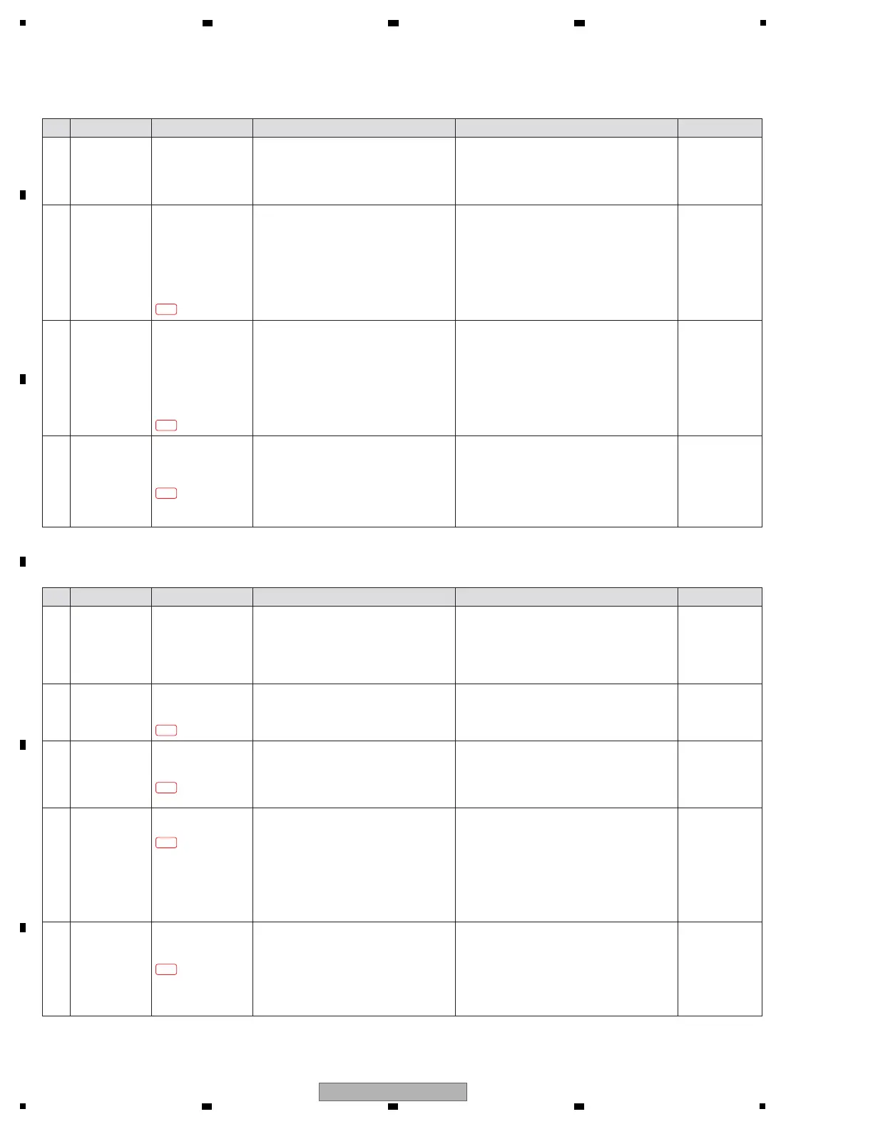
[3-2] No signal is input to the DIGITAL connector
Step Cause Diagnostics Point Item to be Checked Corrective Action Reference
1 Parts defect MAIN Assy
IC2606 (CH1) 11 pin
IC2607 (CH2) 11 pin
IC2703 (CH3) 11 pin
IC2704 (CH4) 11 pin
IC2803 (CH5) 11 pin
IC2804 (CH6) 11 pin
Representative CH1
[Confirmation of the digital input]
Confirm the audio signal (except for fixed
of High or Low) at the diagnostics circuit.
! If no audio signal is input, the circuit around
these parts may be defective. Check for the
status of soldering and replace it.
! If not, go to step 2.
—
Instruction Manual
0 Prior
Confirmation
!
OFF/ON/TALK OVER
selector switch
!
MIC1/2 LEVEL
!
MASTER LEVEL knob
!
MASTER Level
Indicator
! Confirm on the screen that the selector is
set properly.
! Confirm if the MASTER Level Indicator
lights on when an audio signal is input.
! If the MASTER Level Indicator lights on,
OUTPUT may be defective. Refer to
"[4] AUDIO OUTPUT".
! If not, go to step 1.
[3-3] No signal is input to the MIC1/MIC2 connectors
Step Cause Diagnostics Point Item to be Checked Corrective Action Reference
1
Parts defect AIN Assy
MIC*_TRM_IN
Representative MIC1
[Confirmation of the analog input before
MIC1/2 LEVEL]
Confirm the audio signal (sine wave) at the
diagnostics circuit.
! If no audio signal is input, an analog circuit
before this part may be defective.
Check for the status of soldering and replace it.
! If not, go to step 2.
—
2 Parts defect MAIN Assy
IC2610 (CH1) 9 pin
IC2611 (CH2) 9 pin
IC2705 (CH3) 9 pin
IC2706 (CH4) 9 pin
IC2805 (CH3) 9 pin
IC2806 (CH4) 9 pin
Representative CH1
[Confirmation of the digital input]
Confirm the audio signal (except for fixed
of High or Low) at the diagnostics circuit.
! If no audio signal is input, IC2606(CH1),
IC2607(CH2), IC2703(CH3), IC2704(CH4),
IC2803(CH5), IC2804(CH6) and the circuit
around these parts may be defective. Check
for the status of soldering and replace it.
! If not, go to step 3.
—
3 Parts defect MAIN Assy
IC1101 (MAIN CPU/DSP)
CH*_DIGI_DATA
Representative CH1
[Confirmation of the input to MAIN CPU/DSP]
Confirm the audio signal (except for fixed
of High or Low) at the diagnostics circuit.
! If no audio signal is input, IC2610(CH1),
IC2611(CH2), IC2705(CH3), IC2706(CH4),
IC2805(CH5), IC2806(CH6) and the circuit
around these parts may be defective. Check
for the status of soldering and replace it.
! If not, IC1101 and the circuit around it may be
defective. Replace MAIN Assy.
—
2 Parts defect
/
Connection defect
AIN Assy
MIC*_IN
Representative MIC1
[Confirmation of the analog input before
MIC ADC]
Confirm the audio signal (sine wave) at the
diagnostics circuit.
! If no audio signal is input, TRIM circuit or an
analog circuit before this part may be defective.
Check for the status of MTRM Assy connection
and soldering, and replace it.
! If not, go to step 3.
—
4
Connection defect
MAIN Assy
IC1101 (MAIN CPU/DSP)
MIC1_2_DATA
[Confirmation of the input to MAIN CPU/DSP]
Confirm the audio signal (except for fixed
of High or Low) at the diagnostics circuit.
! If no audio signal is input, the connection of
50p FFC between AIN and MAIN Assy may be
defective. Or the circuit to IC1101 may be
defective. Check for the status of connection
and soldering, and replace it.
! If not, IC1101 or the circuit around it may be
defective. Replace MAIN Assy.
—
3 Parts defect AIN Assy
ADAT_MIC
[Confirmation of the digital output after
MIC ADC]
Confirm the audio signal (except for fixed
of High or Low) at the diagnostics circuit.
! If no audio signal is input, the circuit around
MIC ADC may be defective. Confirm the following.
- Soldering state of
IC5203 and around
circuit (V+5A_IN, V+3R3A_*, xRST_ADC,
MCLK_CH*, BICK_CH*, LRCK_CH*)
-
Connection of 50p FFC between AIN and MAIN Assy
-
Connection of 10p wire between AIN and MAIN Assy
If there are no problems, replace IC5203.
! If not, go to step 4.
—
3-2-1
3-3-1
3-3-2
3-3-3
3-3-4
3-2-2
3-2-3
 Loading...