Instruction Manual
0 Prior
Confirmation
!
MASTER MIX button
!
MASTER MIX knob
!
MASTER LEVEL knob
!
MASTER Level
Indicator
! Confirm that MASTER MIX button lights on.
! Confirm that the MASTER MIX LEVEL knob,
and MASTER LEVEL knob are set properly
without MIN.
! Confirm if the MASTER Level Indicator lights
on when an audio signal is input.
! If the MASTER Level Indicator lights on,
OUTPUT may be defective. Refer to
"[4] AUDIO OUTPUT".
! If not, go to step 1.
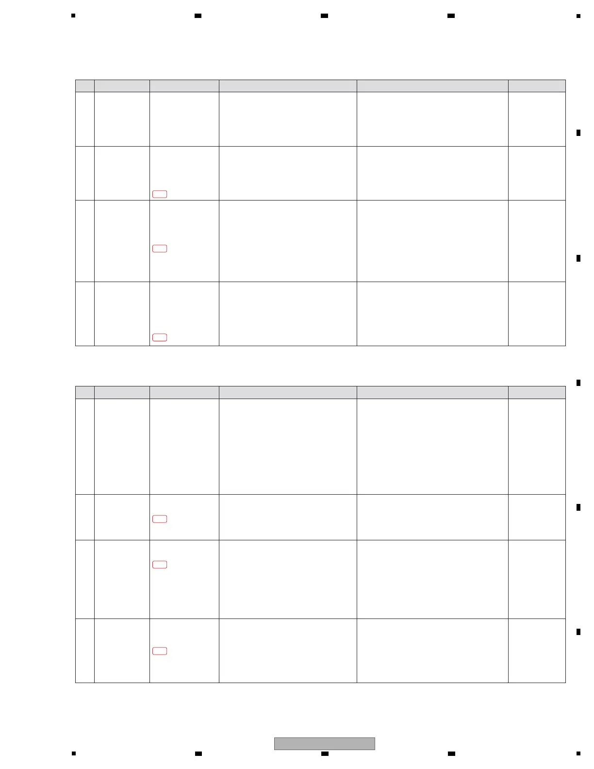
[3-4] No signal is input to the RETURN (EXT1, EXT2) connectors
Step Cause Diagnostics Point Item to be Checked Corrective Action Reference
1
Parts defect
/
Connection defect
AIN Assy
RTN1_LIN/RIN
RTN2_LIN/RIN
Representative
EXT1 RETURN
[Confirmation of the analog input before
RTN1/2 ADC]
Confirm the audio signal (sine wave) at the
diagnostics circuit.
! If no audio signal is input, the wire between
SNRT1/2 and AIN Assy may be defective. Or, an
analog circuit before this part may be defective.
Check for the status of soldering and replace it.
! If not, go to step 2.
—
2 Parts defect AIN Assy
ADAT_RTN1
ADAT_RTN2
Representative
EXT1 RETURN
[Confirmation of the digital output after
RTN1/2 ADC]
Confirm the audio signal (sine wave) at the
diagnostics circuit.
!
If no audio signal is input, the circuit around
RTN1/2 ADC may be defective. Confirm the following.
- Soldering state of
IC4902, IC5002 and around
circuit (V+5A_IN, V+3R3A, xRST_ADC,
MCLK_RTN1/2, BICK_RTN1/2, LRCK_RTN1/2)
-
Connection of 50p FFC between AIN and MAIN Assy
-
Connection of 10p wire between AIN and MAIN Assy
If there are no problems, replace IC4902 or IC5002.
! If not, go to step 3.
—
3 Parts defect
/
Connection defect
MAIN Assy
IC1101 (MAIN CPU/DSP)
RTN1_DATA
RTN2_DATA
Representative
EXT1 RETURN
[Confirmation of the input to MAIN CPU/DSP]
Confirm the audio signal (except for fixed
of High or Low) at the diagnostics circuit.
! If no audio signal is input, the connection of
50p FFC between AIN and MAIN Assy may be
defective. Or the circuit to IC1101 may be
defective. Check for the status of connection
and soldering, and replace it.
! If not, IC1101 or the circuit around it may be
defective. Replace MAIN Assy.
—
Instruction Manual
0 Prior
Confirmation
! MODE select switch
! CH SELECT select
switch
! RETURN ON/OFF
button
! MULTI I/O LEVEL Knob
! CH Fader
! MASTER LEVEL Knob
! MASTER Level
Indicator
! Confirm that the mode is set to
1/4"JACK.
! Confirm that RETURN_ON/OFF button is
set to ON.
!
Confirm that
MULTI I/O LEVEL Knob,
CH Fader, MASTER LEVEL Knob are set
properly without MIN.
!
Confirm if the MASTER Level Indicator
lights on when an audio signal is input.
* RETURN need to input the audio signal
to not only Rch but also Lch at the
diagnosis.
! If the MASTER Level Indicator lights on,
OUTPUT may be defective. Refer to
"[4] AUDIO OUTPUT".
! If not, go to step 1.
[3-5] No signal is input to the RETURN (MULTI I/O) connector
Step Cause Diagnostics Point Item to be Checked Corrective Action Reference
1 Parts defect
/
Connection defect
AIN Assy
RTN3_LIN/RIN
[Confirmation of the analog input before
RTN3 ADC]
Confirm the audio signal (sine wave) at the
diagnostics circuit.
!
If no audio signal is input, the wire between
SNRT3
and AIN Assy may be defective. Or, an
analog circuit before this part may be defective.
Check for the status of soldering and replace it.
! If not, go to step 2.
—
2 Parts defect AIN Assy
ADAT_RTN3
[Confirmation of the digital output after
RTN3 ADC]
Confirm the audio signal (sine wave) at the
diagnostics circuit.
!
If no audio signal is input, RTN3 ADC and the circuit
around it may be defective. Confirm the following.
- Soldering state of
IC5102 and around
circuit (V+5A_IN, V+3R3A, xRST_ADC,
MCLK_RTN3, BICK_RTN3, LRCK_RTN3)
-
Connection of 50p FFC between AIN and MAIN Assy
-
Connection of 10p wire between AIN and MAIN Assy
If there are no problems, replace IC5102.
! If not, go to step 3.
—
3 Parts defect
/
Connection defect
MAIN Assy
IC1101 (MAIN CPU/DSP)
RTN3_DATA
[Confirmation of the input to MAIN CPU/DSP]
Confirm the audio signal (except for fixed
of High or Low) at the diagnostics circuit.
! If no audio signal is input, the connection of
50p FFC between AIN and MAIN Assy may be
defective. Or the circuit to IC1101 may be
defective. Check for the status of connection
and soldering, and replace it.
! If not, IC1101 or the circuit around it may be
defective. Replace MAIN Assy.
—
3-4-1
3-4-2
3-4-3
3-5-1
3-5-2
3-5-3
 Loading...