1 Output
Confirmation
MASTER1
MASTER2
BOOTH
Confirm the connectors that do not output
signals.
! If all connectors do not output, go to step 2.
! If only MASTER1 not output, go to step 5.
! If only MASTER2 not output, go to step 6.
! If only BOOTH not output, go to step 7.
2 Parts defect MAIN Assy
DAC_xRST
IC2101 7 pin
[Confirmation of the RESET input signal to DAC]
Confirm that the signal of 7 pin of IC2101
is LOW.
! If the signal is LOW, go to step 3.
! If HI, the DAC_xRST circuit may have a
soldering defect. Check for the status of
soldering and replace it.
3 Parts defect MAIN Assy
IC2101
41/42 pin, 43/44 pin,
45 pin, 46pin, 19 pin
[Confirmation of the digital input to DAC]
Confirm the audio signal and CLK (except
for fixed of High or Low) at the diagnostics
circuit.
! If no audio signal is input, MAIN CPU/DSP
(IC1101) or AUDIO_CLK (IC2002) may be
defective. Replace MAIN Assy.
! If not, go to step 4.
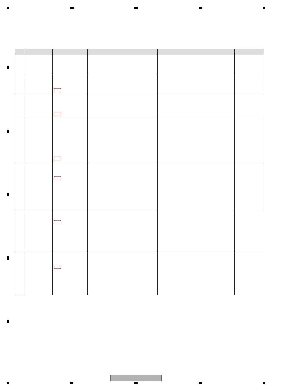
[4] AUDIO OUTPUT
[4-1] No signal is output from the MASTER1/MASTER2/BOOTH
Step Cause Diagnostics Point Item to be Checked Corrective Action Reference
—
—
—
4 Parts defect MAIN Assy
IC2103 1 pin, 7 pin
(MAS_L-/MAS L+)
IC2104 1 pin, 7 pin
(MAS_R-/MAS_R+)
IC2301 1 pin, 7 pin
(BTH_L-/BTH_L+)
IC2302 1 pin, 7 pin
(BTH_R-/BTH_R+)
[Confirmation of the analog output from DAC]
Confirm the audio signal (sine wave) at the
diagnostics circuit.
! If no audio signal is input, IC2101 and the
circuit around it may be defective. Check for
the status of soldering and replace it.
—
5 Parts defect AOUT Assy
IC5501 1 pin, 7 pin
IC5502 1 pin, 7 pin
[Confirmation of the analog output of MASTER1]
Confirm the audio signal (sine wave) at the
diagnostics circuit.
! If no audio signal is input, an analog circuit
before this part may be defective.
Check for the status of soldering of the
following places and replace it.
- IC5501
- IC5502
- The circuit around its
! If not, RY5501, RY5502, Q5502, Q5503,
Q5504, Q5505 and the circuit around its may
be defective. Check for the status of soldering
and replace it.
6 Parts defect AOUT Assy
IC5601 1 pin, 7 pin
[Confirmation of the analog output of MASTER2]
Confirm the audio signal (sine wave) at the
diagnostics circuit.
! If no audio signal is input, an analog circuit
before this part may be defective.
Check for the status of soldering of the
following places and replace it.
- IC5601
- The circuit around it
! If not, Q5601, Q5602 and the circuit around its
may be defective. Check for the status of
soldering and replace it.
—
—
7 Parts defect AOUT Assy
IC5701 1 pin, 7 pin
IC5702 1 pin, 7 pin
[Confirmation of the analog output of BOOTH]
Confirm the audio signal (sine wave) at the
diagnostics circuit.
! If no audio signal is input, an analog circuit
before this part may be defective.
Check for the status of soldering of the
following places and replace it.
- IC5701
- IC5702
- The circuit around its
! If not, Q5701, Q5702 ,Q5703, Q5704 and the
circuit around its may be defective. Check for
the status of soldering and replace it.
—
4-1-2
4-1-3
4-1-4
4-1-5
4-1-6
4-1-7
 Loading...