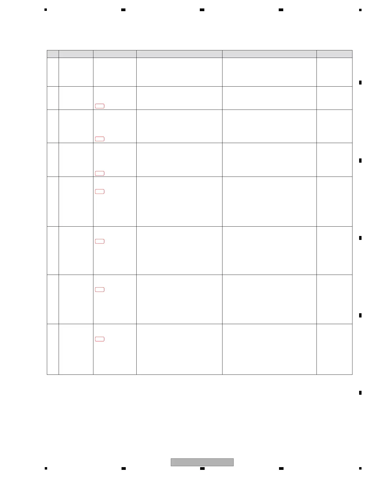
1 Output
Confirmation
REC
EXT1 SEND
EXT2 SEND
MULTI I/O SEND
Confirm the connectors that do not output
signals.
! If all connectors do not output, go to step 2.
! If only REC not output, go to step 5.
! If only EXT1 SEND not output, go to step 6.
! If only EXT2 SEND not output, go to step 7.
! If only MULTI I/O SEND not output, go to step 8.
2 Parts defect MAIN Assy
DAC_xRST
IC2401 5 pin
[Confirmation of the RESET input signal to DAC]
Confirm that DAC_RESET signal is HI.
! If the signal is HI, go to step 3.
! If LOW, the DAC_xRST circuit may have a
soldering defect. Check for the status of
soldering and replace it.
3 Parts defect MAIN Assy
IC2401
1 pin, 2 pin, 3 pin,
4 pin, 9 pin, 10 pin,
11 pin
[Confirmation of the digital input to DAC]
Confirm the audio signal and CLK (except
for fixed of High or Low) at the diagnostics
circuit.
! If no audio signal is input, MAIN CPU/DSP
(IC1101) or AUDIO_CLK (IC2002) may be
defective. Replace MAIN Assy.
! If not, go to step 4.
[4-2] No signal is output from the REC/SEND (EXT1, EXT2, MULTI I/O)
Step Cause Diagnostics Point Item to be Checked Corrective Action Reference
—
—
—
4 Parts defect MAIN Assy
IC2401
17 pin, 18 pin, 19 pin,
20 pin, 21 pin, 22 pin,
24 pin, 25 pin
[Confirmation of the analog output from DAC]
Confirm the audio signal (sine wave) at the
diagnostics circuit.
! If no audio signal is input, IC2401 and the
circuit around it may be defective. Check for
the status of soldering and replace it.
—
5 Parts defect AOUT Assy
IC5602 1 pin, 7 pin
[Confirmation of the analog output of REC]
Confirm the audio signal (sine wave) at the
diagnostics circuit.
! If no audio signal is input, an analog circuit
before this part may be defective.
Check for the status of soldering of the
following places and replace it.
- IC5602
- The circuit around it
! If not, Q5603, Q5604 and the circuit around its
may be defective. Check for the status of
soldering and replace it.
6 Parts defect AOUT Assy
IC5801 1pin, 7pin
[Confirmation of the analog output of EXT1 SEND]
Confirm the audio signal (sine wave) at the
diagnostics circuit.
! If no audio signal is input, an analog circuit
before this part may be defective.
Check for the status of soldering of the
following places and replace it.
- IC5801
- The circuit around it
! If not, Q5801, Q5802 and the circuit around its
may be defective. Check for the status of
soldering and replace it.
—
—
7 Parts defect AOUT Assy
IC5901 1 pin, 7 pin
[Confirmation of the analog output of EXT2 SEND]
Confirm the audio signal (sine wave) at the
diagnostics circuit.
! If no audio signal is input, an analog circuit
before this part may be defective.
Check for the status of soldering of the
following places and replace it.
- IC5901
- The circuit around it
! If not, Q5901, Q5902 and the circuit around its
may be defective. Check for the status of
soldering and replace it.
—
8 Parts defect AOUT Assy
IC6001 1 pin, 7 pin
[Confirmation of the analog output of
MULTI I/O SEND]
Confirm the audio signal (sine wave) at the
diagnostics circuit.
! If no audio signal is input, an analog circuit
before this part may be defective.
Check for the status of soldering of the
following places and replace it.
- IC6001
- The circuit around it
! If not, Q6001, Q6002 and the circuit around its
may be defective. Check for the status of
soldering and replace it.
—
4-2-2
4-2-3
4-2-4
4-2-5
4-2-6
4-2-7
4-2-8
 Loading...