5-1-1
5-1-2
5-1-3
0
Confirmation of
the inner wiring
connection
Confirm the wire between LCD Module,
LCDB Assy, UCOM Assy and MAIN Assy.
[5] LCD
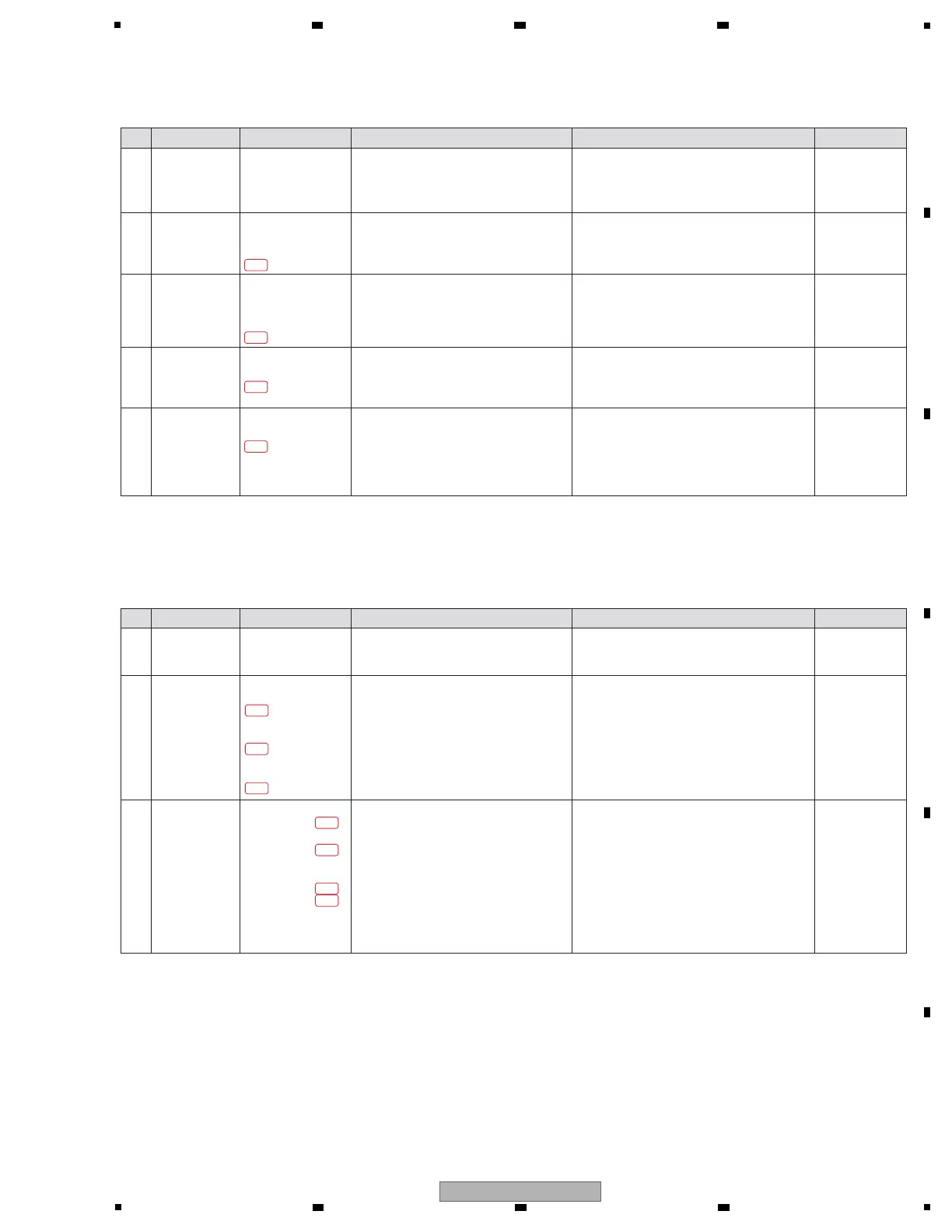
[5-1] LCD is no display (but LED is lighting on)
Step Cause Diagnostics Point Item to be Checked Corrective Action Reference
——
1
Backlight power
defect
Confirm the voltage of the backlight power
supply.
[4-4] No signal is output from the DIGITAL MASTER OUT
Step Cause Diagnostics Point Item to be Checked Corrective Action Reference
3 Parts defect MAIN Assy
IC2904
1 pin, 2 pin, 3 pin,
4 pin
[Confirmation of the digital input to DIT]
Confirm the audio signal (except for fixed
of High or Low) at the diagnostics circuit.
! If no audio signal is input, IC2901, IC2902 and
the circuit around its may be defective. Check
for the status of soldering and replace it.
! If not, go to step 4.
—
4 Parts defect MAIN Assy
IC2904 16 pin
[Confirmation of the digital output from DIT]
Confirm the audio signal (except for fixed
of High or Low) at the diagnostics circuit.
! If no audio signal is input, IC2904 and the
circuit around it may be defective. Check for
the status of soldering and replace it.
! If not, go to step 5.
—
5 Parts defect MAIN Assy
IC2905 6 pin, 7 pin
LCDB Assy
L8901[NM] LCD_LED_A
UCOM Assy
TP LCD_LED_A
MAIN Assy
TP LCD_LED_A
[Confirmation of the digital output from
DRIVER IC]
Confirm the audio signal (except for fixed
of High or Low) at the diagnostics circuit.
! If no audio signal is input, IC2905 and the
circuit around its may be defective. Check for
the status of soldering and replace it.
! If not, VL2901 and the circuit around it may be
defective. Check for the status of soldering and
replace it.
! If there is no problem, go to step 2.
! If there is a problem in the middle of the
circuit, confirm the wiring. Repair by soldering
if necessary.
! If there is no voltage in the MAIN Assy, the
LCD Backlight circuit may be defective.
Check for the status of soldering of Q1301,
Q1302, Q1303, Q1304, Q1305, Q1306, Q1307
and the circuit around its, and replace it.
5-2-1
5-2-2
5-2-3
5-2-4
2 RESET signal
defect
[Confirmation of the RESET signal]
Confirm that LCD_xRST signal is HI.
[
Confirmation of the system
CLK of the
MAIN CPU/DSP]
Check the following voltages at the
diagnostics point.
C1514 + side (1.8 V 24 MHz)
LCDB Assy
TP
UCOM Assy
TP
MAIN Assy
R1579
C1514 + side
! If the signal is HI, go to step 3.
! If LOW, the LCD_xRST circuit may have a
soldering defect. Check for the status of
soldering and replace it.
! If the voltage is not confirmed correctly, the
circuit or the parts between
X1501
and
IC1101
may be defective.
If the parts other than IC1901 are defective,
replace its. If IC1901 is defective, replace
MAIN Assy.
LCD is controlled by MAIN CPU/DSP(IC1101).
—
—
—
1 Parts defect MAIN Assy
DOUT_SRC_DIT_xRST
[Confirmation of the RESET signal]
Confirm that DOUT_SRC_DIT_xRST signal
is HI.
! If the signal is HI, go to step 2.
! If LOW, the DOUT_SRC_DIT_xRST circuit may
have a soldering defect. Check for the status
of soldering and replace it.
—
2 Parts defect MAIN Assy
IC2902
7 pin, 8 pin, 9 pin
[Confirmation of the digital input to SRC]
Confirm the audio signal and CLK (except
for fixed of High or Low) at the diagnostics
circuit.
! If no audio signal is input, MAIN CPU/DSP
(IC1101) or AUDIO_CLK (IC2002) may be
defective. Replace MAIN Assy.
! If not, go to step 3.
—
—
4-4-2
4-4-3
4-4-4
4-4-5
 Loading...