10.83
WAVEFORMS
10.83
WAVEFORMS
5-3-1
5-3-2
5-3-3
5-3-4
5-3-5
5-3-6
5-3-7
5-3-8
5-3-9
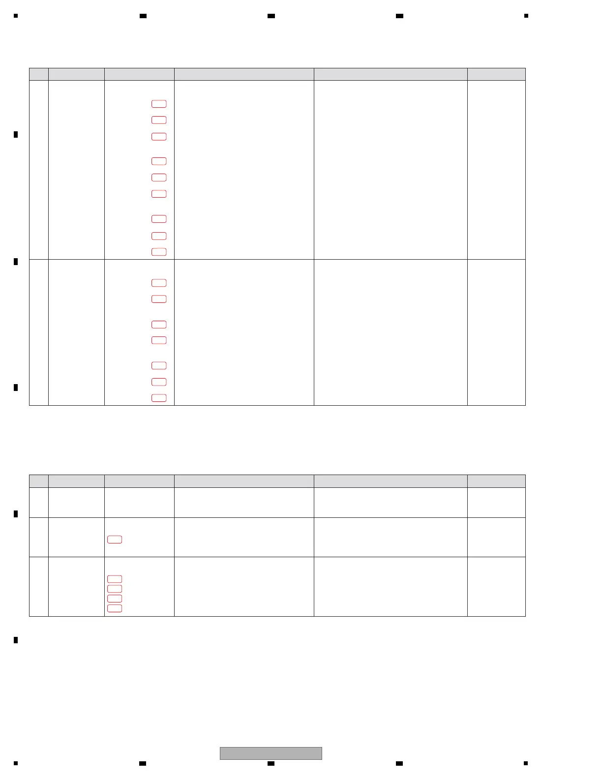
Step Cause Diagnostics Point Item to be Checked Corrective Action Reference
3 Signal defect
Confirm the square wave of LCD_DCLK,
LCD_HSYNC and LCD_VSYNC.
LCD_DCLK
LCDB Assy
R8920
UCOM Assy
TP
MAIN Assy
R1354
LCD_HSYNC
LCDB Assy
R8921
UCOM Assy
TP
MAIN Assy
R1341
LCD_VSYNC
LCDB Assy
R8910
UCOM Assy
TP
MAIN Assy
R1353
5-4-1
5-4-2
5-4-3
5-4-4
5-4-5
5-4-6
5-4-7
LCD_SCL
LCDB Assy
TP
UCOM Assy
R8422
LCD_SDA
LCDB Assy
TP
UCOM Assy
R8425
LCD_xCS
LCDB Assy
TP
UCOM Assy
TP
MAIN Assy
R1568
! If the voltage of the all points are confirmed
correctly, go to step 4.
!
If not,
the diagnosed circuits may be defective.
Check for the status of soldering and replace it.
4 Signal defect
Confirm the square wave of
LCD_SCL,
LCD_SDA and LCD_xCS
when startup.
! If the voltage of the all points are confirmed
correctly, LCD module may be defective.
Replace it
!
If not,
the diagnosed circuits may be defective.
Check for the status of soldering and replace it.
6-2-1
1 Wire Connection
defect
Confirm that the touch panel FPC is
properly inserted into CN8902.
[6] Touch panel
[6-1] No work of the Touch panel
Step Cause Diagnostics Point Item to be Checked Corrective Action Reference
2 PNL1 UCOM
defect
Confirm the touch panel input signal at
84 pin, 82 pin of IC8406 when you touch
the center of the screen.
UCOM Assy
TP
LCDB Assy
! If there is a problem with the waveform,
go to step 3.
! If not, IC8406 may be defective. Replace it.
6-3-1
6-3-2
6-3-3
6-3-4
3
Touch panel defect
/Circuit defect
Confirm the touch panel control signal at
1 pin, 2 pin, 3 pin, 4 pin of CN8902.
LCDB Assy
TP
! If there is a problem with the signal, the circuit
between IC8406 and CN8902 may be
defective. Replace the parts.
! If not, the touch panel have a defective.
Replace it.
Insert the FPC vertically and lock it firmly.
Touch panel signal is controlled by PNL1 UCOM (IC8406).
—
—
—
 Loading...