—Check the following voltages at the
diagnostics point while connected to MIDI
device.
[Power supply of MIDI circuit]
V+5D_MIDI (5 V)
[The signal circuit of MIDI circuit]
MIDI_OUT_AM (3.3 V amplitude)
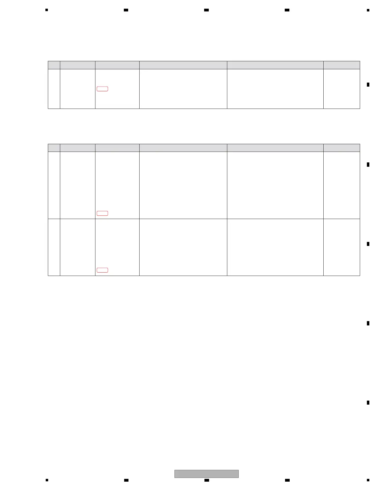
1 Power defect or
signal defect of
MIDI circuit
MAIN Assy
R3005 (V+5D_MIDI)
TP MIDI_OUT_AM
[11] DIN MIDI
[11-1] MIDI device does not recognize the unit
Step Cause Diagnostics Point Item to be Checked Corrective Action Reference
! If the voltage is confirmed correctly, replace
MAIN Assy.
! If not, the circuit or the parts between IC401
and 4 pin of JA3001 may be defective.
If the parts other than IC401 are defective,
replace its. If IC1101 is defective, replace
MAIN Assy.
11-1-1
—
[SPI communication circuit after BUS BUFFER SW]
UPD_PNL1_PNL2 (3.3 V)
MDSP_PNL2_XINT (3.3 V amplitude)
MDSP_PNL2_SCK (3.3 V amplitude)
MDSP_PNL2_MOSI (3.3 V amplitude)
MDSP_PNL2_MISO (3.3 V amplitude)
Between R8579 and R8588 (MDSP_PNL2_MISO)
1
SPI communication
error between
BUS BUFFER SW
(IC8408) and
PNL2 UCOM
(IC8409)
UCOM Assy
IC8409 76 pin
(UPD_PNL1_PNL2)
IC8408 19 pin
(MDSP_PNL2_XINT)
IC8408 3 pin
(MDSP_PNL2_SCK)
IC8408 5 pin
(MDSP_PNL2_MOSI)
Between R8579 and R8588
(MDSP_PNL2_MISO)
[12] Firmware update
[12-1] Firmware cannot be updated
Step Cause Diagnostics Point Item to be Checked Corrective Action Reference
!
If the signal can be confirmed, go to step 2.
! If not, the circuit or the parts between IC8408
and IC8409 may be defective. Replace the
defective parts.
12-1-1
—[UPD_PNL1_MDSP line]
UPD_PNL1_MDSP (3.3 V)
2
Communication
error of
UPD_PNL1_MDSP
line
UCOM Assy
Between 34 pin of
IC8406, R8574 and
CN8413
MAIN Assy
Between CN7, R23,
R1581 and IC1101
(UPD_PNL1_MDSP)
!
If the signal can be confirmed,
perform
a crosscheck of MAIN
Assy and UCOM Assy,
and replace the defective Assy.
! If not, the parts may be defective. Replace its.
12-1-2
 Loading...