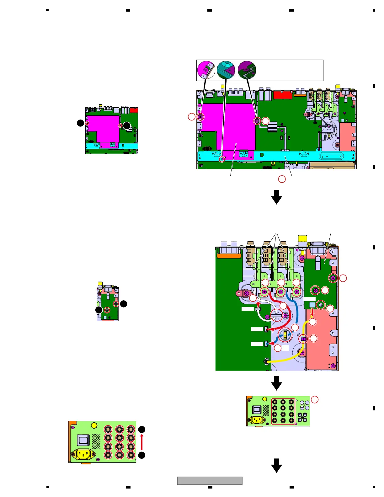
[3] Chassis Section (Bottom part)
[3-1] Shield plate and Stay
1 Remove the 2 screws and then remove the
Shield plate.
(BBZ30P060FTC)
2 Remove the Stay.
1
3
4
3
3
1
2
2
222
1
×2×2
[3-2] PSWB Assy, SNRT1, 2, 3 Assy
1 Release the 3 Jumper wire stylings.
2 Remove the 5 screws.
(BBZ30P060FTC)
3 Disconnect the 4 connectors.
(CN5404, 5405, 5406, 7701)
4 Unlock the PCB holder.
5 Remove the 12 nuts and 12 washers.
• Rear view
Shield plate Stay
PSWB AssySNRT1, 2, 3 Assy
CN7701CN7701
CN5405
CN5405
CN5406
CN5406
CN5404
CN5404
Notes on assembling
Confirm that three hooks
are inserted.
1
1
1
4
2
2
Screw tightening order
Screw tightening order
Nut and Washer tightening order
1
2
1
5
×12×12