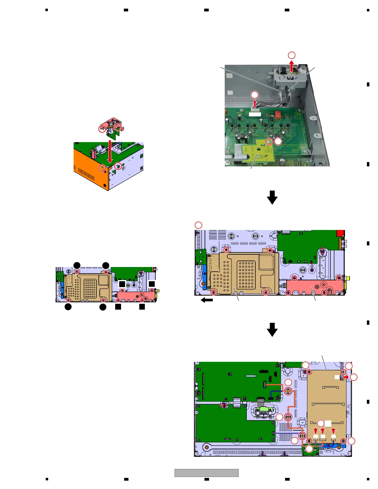
[3-3] HPJK, HPJM and FGP2 Assys
1 Disconnect the one connector.
(CN6353)
2 Remove the HPJK and HPJM Assy with Stay.
3 Remove the one screw and then remove the
FGP2 Assy.
(BBZ30P060FTC)
[3-4] SW POWER SUPPLY
1 Remove the 8 screws and then remove the
Cover and Shield case.
(BBZ30P060FTC)
2 Release the 3 Jumper wires stylings.
3 Disconnect the 4 connectors.
(P1, 2, 3, 4)
4 Remove the 3 screws.
(ABZ30P060FTC)
5 Unlock the Spacer and then remove the
SW POWER SUPPLY.
Cover
Front
Shield case
SW POWER SUPPLY
P1P1
P3
P3 P4P4 P2P2
4
3
2
1
Screw tightening order
g Notes on assembling
Put the slits of the stay to the hooks of the chassis.
1
2
2
2
4
4
5
3
3
4
×8×8
12
3
4
×3×3
HPJK AssyHPJM Assy
FGP2 Assy
CN6353CN6353
Notes on assembling
Attach it while being careful about the
directions fixing FGP2 Assy.
1
2
3
 Loading...