DLM-600 installer & user manual Rev. 1.3 16-11-2011 10 / 39
RETURN TO FACTORY DEFAULT
To set the DLM-600 back to the factory defaults the DLM-600 must first be powered down. Then press
and hold the S4 button and connect the power again. Hold the S4 button until the OP2 led illuminates.
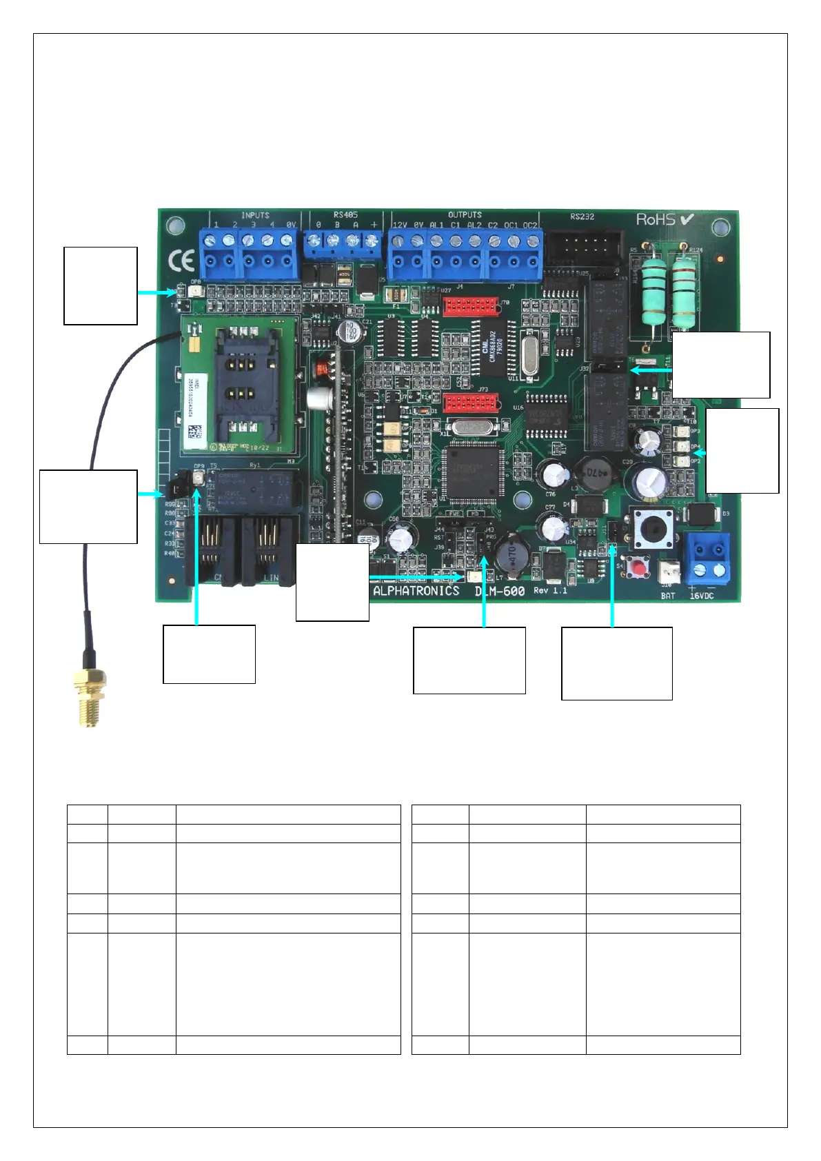
JUMPERS AND LED’S
figure 1.
figure 2. Jumpers and LED’s
figure 3. LED table and Jumper table
Function when LED illuminates
Dialer is transmitting an alarm
Pin 1 (top) en 2 – open
Pin 2 and 3 (bottom) –
short circuited
Message in buffer / GPRS dialer ready
GSM module:
Fast flashing: GSM module is starting
up
Slow flashing: GSM/GPRS module is
ready
On continuous: GSM (Voice) is active
Pin 1 (left) and 2– enable
Pin 2 and 3 (right)– protect
Pin 1(left) and 2 – run
Pin 2 and 3 (right) - flash
PSTN Line and CMK connected
LED’s OP3,
OP4, OP2:
zie LED
tabel
(figure 3)
Jumper J11 for
override
tamper
switch
Jumper J32
voor keuze
n.o. of n.c. van
relais 1 en 2
Jumpers J39, J40,
J43 and J44; see
table
Jumper J71
for
PSTN loop
monitoring
LED OP8:
see LED
table
(figure 3)
LED OP5:
see LED
table
(figure 3)
LED OP9:
see LED table
(figure 3)