EasyManua.ls Logo

Ametek Drexelbrook ThePoint Series - User Manual

Ametek Drexelbrook ThePoint Series
70 pages
Print Icon
To Next Page IconTo Next Page
Loading...
Leader in
Level Measurement
Installation and
Operating Instructions
ThePoint™ Series Point Level Switch
Auto Calibration or Manual Calibration
Selectable
Telephone: +1 215-674-1234
Fax: +1 215-674-2731
E-mail: drexelbrook.service@ametek.com
Website: www.drexelbrook.com

Questions and Answers

  • M
    Mrs. Dawn MckayAug 2, 2025
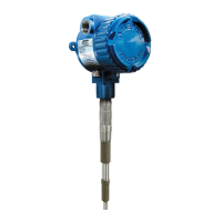
    What to do if Ametek Drexelbrook ThePoint Measuring Instruments readings are too low?
    • C
      corey99Aug 2, 2025
      If the readings on your Ametek Drexelbrook Measuring Instruments are lower than expected, you should first check if the tank is full or if there's a significant coating present on the sensor. Additionally, cleaning the sensor and re-measuring the sensor resistances might resolve the issue.
  • C
    Charles ArroyoAug 7, 2025
    What to do if Ametek Drexelbrook ThePoint unit appears dead?
    • D
      Danielle GuerreroAug 7, 2025
      If your Ametek Drexelbrook Measuring Instruments unit appears dead, try removing and then reapplying power. If that doesn't work, press the reset button. Observe the two LEDs flashing for about 60 seconds, after which the green LED should light up. Then, touch the sensing element with your finger; if the circuit board is working, reinstall the instrument and press reset.
  • T
    Tracy LambertAug 12, 2025
    Why Ametek Drexelbrook ThePoint reading is zero?
    • R
      Randall Baird MDAug 12, 2025
      A zero Ohms reading on your Ametek Drexelbrook Measuring Instruments typically indicates a metal-to-metal short circuit. Check for any contact between the sensor and the tank wall, mounting nozzle, or any other tank structure.
  • C
    Craig MillerAug 17, 2025
    What to do if ThePoint is stuck on Ametek Drexelbrook ThePoint Measuring Instruments?
    • G
      georgebentleyAug 17, 2025
      If ThePoint on your Ametek Drexelbrook Measuring Instruments is stuck in one state, begin by removing power and then disconnecting the coax cable that connects the sensing element to the electronic unit. After this, reapply power. If ThePoint changes state with the sensing element disconnected, the sensing element is likely faulty.
  • C
    Chris HillAug 22, 2025
    Why does ThePoint change state when moving jumper on Ametek Drexelbrook Measuring Instruments?
    • S
      Steven KirbyAug 23, 2025
      If ThePoint changes state while moving the jumper, but not when touching the sensing element on your Ametek Drexelbrook Measuring Instruments, the integral cable is likely faulty.
  • N
    Nicole LeblancAug 27, 2025
    What to do if ThePoint fails all tests on Ametek Drexelbrook ThePoint?
    • C
      Charles WilliamsAug 27, 2025
      If ThePoint fails all the tests on your Ametek Drexelbrook Measuring Instruments, the instrument is likely faulty. Use a replacement electronic unit to determine the exact fault.

Summary

Section 1: Introduction

1.1 System Description

Describes the technology and operation of the ThePoint Series.

1.2 Technology Explained

Explains capacitance and RF admittance technology used in the device.

1.3 Model Number Configuration

Technology Options

Details measurement technology options for model configuration.

Input and Output Options

Specifies power supply and relay output options.

Housing and Electronics Configurations

Details enclosure types, certifications, and electronics.

Sensing Element Types and Applications

Describes various sensing element types and their applications.

Application-Specific Model Numbers

Model numbers for specific applications like fly ash and chute detection.

Mounting Type Options

Details available mounting configurations and connection types.

1.4 Housing Dimensions

Section 2: Installation

2.1 Unpacking Instructions

Instructions for unpacking the product and checking contents.

2.2 General Mounting Guidelines

General guidelines for mounting and installation.

2.2 Explosion Proofing Considerations

Covers explosion proofing and installation considerations.

2.2 Flush-Mounted Sensing Element Installation

Specific instructions for flush-mounted elements in chutes.

2.3 Flush-Mounted Sensing Elements

Specific instructions for flush-mounted elements in chutes.

2.4 Input Wiring

Details universal power supply wiring.

2.5 Output Wiring - Relay Version

Explains how to wire the relay output.

2.6 Output and LED Status

Describes the meaning of status LEDs and relay conditions.

2.7 Electronic Unit Features

Details the electronic unit's features and adjustments.

2.7.1 Time Delay Adjustment

Explains time delay adjustment from 0 to 60 seconds.

2.7.2 Time Delay Action

Describes forward/reverse acting time delay.

2.7.3 Failsafe Modes

Explains failsafe modes (HLFS, LLFS).

2.7.4 ReCal Button and Memory Reset

Instructions for recalibration and memory reset.

2.8 Spark Protection

Discusses protection against static discharge.

2.9 Sensing Element Connection (Integral)

How to connect integral sensing elements to the unit.

2.9 Sensing Element Connection (Remote)

Covers remote sensing element connections to the unit.

2.10 Calibration Overview

Introduction to calibration modes.

2.10.1 Selecting Calibration Mode

Guide to choosing calibration modes for applications.

2.10.1 Application Guide for Calibration

Application guide for selecting calibration modes.

2.10.2 Using Auto-Calibration Mode

How to use the auto-calibration mode.

2.10.3 Using Manual Calibration Modes

Instructions for using manual calibration modes #7 and #8.

2.10.3 Manual Calibration Steps

Manual calibration steps and potentiometer adjustment.

2.10.3 Manual Calibration Material Guide

Table for manual calibration based on material type.

2.10.3 Calibration Notes

Notes on calibration and nonvolatile memory function.

2.10.4 Accessing Calibration Modes

How to switch between different calibration modes.

2.10.4 Calibration Code Definitions

Definition of calibration codes used in the system.

Section 3: Troubleshooting

3.1 Testing Sensing Element

How to test the sensing element's resistance.

3.2 Testing Electronic Unit

Steps to test the electronic unit's functionality.

3.3 Testing Relay Circuits

Procedures for testing relay circuits.

3.4 Over Range Troubleshooting

Troubleshooting for over range condition.

3.5 Under Range Troubleshooting

Troubleshooting for under range condition.

3.6 Testing Integral Cable

How to test the integral cable connection.

3.7 Testing Remote Cable

How to test the remote cable connection.

3.8 Factory Assistance

Information on contacting the factory for support.

3.9 Field Service

Information on field service availability.

3.10 Customer Training

Details on customer training seminars.

3.11 Equipment Return Procedures

Procedures for returning equipment for repair or credit.

3.12 Troubleshooting Guide

A guide to common symptoms and their solutions.

Section 4: Specifications

4.1 Approvals Available

Lists certifications and approvals for the product.

Section 5: Control Drawings

5.1 FM; FMc Control Drawings

FM/FMc control diagrams for installation.

5.2 ATEX Control Drawings

ATEX control diagrams for installation.

5.3 Heavy Duty Spark Protection

Diagrams for installing heavy-duty spark protectors.

5.4 Adding a Padded Capacitor

Instructions for adding a padding capacitor for tuning.

5.5 Dual Seal Assembly for 700 Series

Control drawing for dual seal assembly.

Appendix A: Sensing Element Modification

Shortening or Lengthening Sensing Element

Instructions for modifying sensing element length.

CE Installation Supplement

Purpose and Definitions

Purpose and definitions for CE compliance.

I;O Sensor;Measurement;Control Ports Wiring

Wiring requirements for sensor ports.

I;O AC Power Port Wiring

Wiring requirements for AC power ports.

Remote Installation Requirements

Requirements for remote installation.

Housing and Sensor Mounting Requirements

Housing and sensor mounting rules for CE compliance.

CE Installation Comments

General comments on CE installation requirements.

Ametek Drexelbrook ThePoint Series Specifications

General IconGeneral
BrandAmetek Drexelbrook
ModelThePoint Series
CategoryMeasuring Instruments
LanguageEnglish