Installation & Start-Up | 3-5
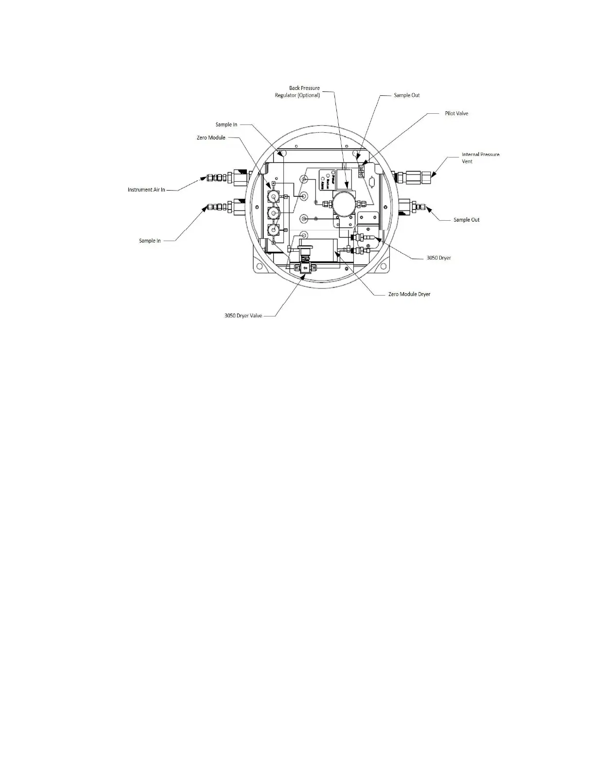
Figure 3-2a.
Threaded Enclosure
Analyzer Arrangement
Electrical Connections Power Signal Junction Boxes
1. Access terminal in power signal Junction Box.
2. Connect the 4 to 20 mA analog output and alarm contacts from the ter-
minal block to user recording equipment.
3. Connect serial communication from analyzer to the PC being used for
customer parameter setup.
RS-232 Out - Connect RS-232 cable connector on the sample system plate.
RS-485 In - Connect RS-485 in cable to the terminal block.
OR
RS-485 Out - Termination plug is installed at the factory. Remove the RS-485
termination plug from the RS-485 Out connection when communicating
with multiple analyzers except for the last analyzer in a chain.
4. Connect line power to analyzer.
5. When installing external wiring to the junction box, use appropiate
thorough-wall bulkhead connections suitable for the hazaradous area
classiication and the environmental conditions encountered.

 Loading...


