Modbus Communication Interface | A-13
ANALYZER CONFIGURATION OPERATIONS
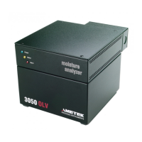
In this section, coniguring the analyser with the MODBUS is discussed. The 3050 analyzer
shipped ready to communicate via MODBUS using the serial communications port. While
the 3050 analyzer can be completely conigured using the MODBUS connection, AMETEK
recommends the use of the 3050 Conigurator software for coniguring the analyser. The
3050 conigurator software is also compatible with MODBUS RTU. Switching protocols
can be accomplished with the 3050 Conigurator software or with the AMETEK “ProtocolS-
witch” utility, which is discussed in the next section.
Figure A-5.
Alarm Register Value.
Figure A-6.
Holding Register Values.
ALARM NAME System State Bit Number of blinks Comment
Memory Failure Bit 4 1 System Alarm
Sensor Failure Bit 5 2 Frequency&Sensor Access
Calibration Failure Bit 6 3 Span Out of Limit
Oven Temperature Out Bit 7 4 Temperature Out of Limit
Flow Out of Range Bit 8 5 System Alarm
Battery Low Bit 9 6 BatteryState
Reference Gas Alarm Bit 10 7 Set if Delta Freq < -0.3Hz
Warnings
Enclosure Temperature Bit 11 8 Temp > 70 degrees C
Moisture Generator Date Bit 12 N/A Good for 2 years
Dryer Alarm Bit 13 10 Exceeding PPM Hours
Concentration Alarm Bit0 – Bit1 11 Concentration out of range
Invalid Reading Bit2 11 Verification or System Alarm
Process pressure Bit3 11 Process pressure out of limits
Value COMMAND DESCRIPTION
71 Start Verification Cycle
76 Load Sensor Memory
81 Quit Verification Cycle
82 Reset Analyzer
84 Start/Stop Test Mode
90 Start Zero Cycle

 Loading...


