AXB-F117 Stealth 1 Camera Controller Installation 15
•
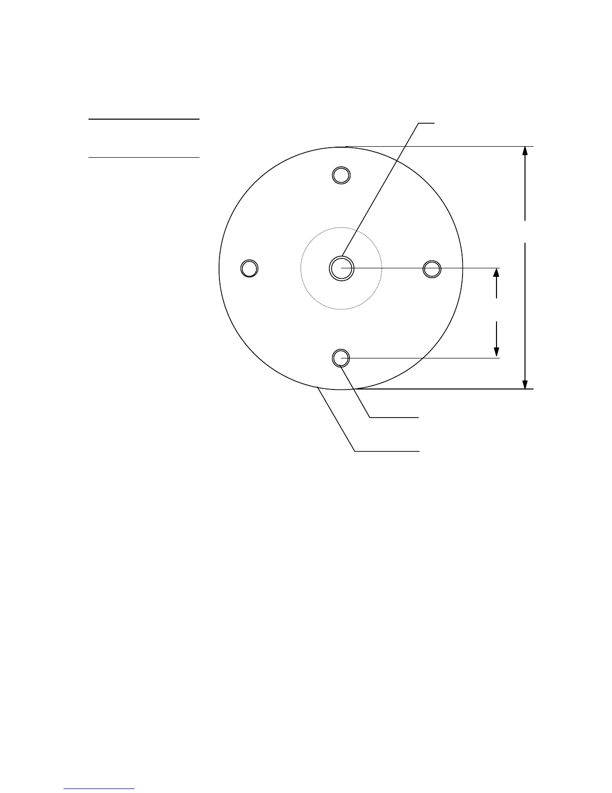
5/16" (7.9 mm) typical of four
on 3.00" (76.2 mm) diameter
•
1/4" (6.3 mm) - 20 thread
•
7/16" (11.1 mm) diameter for
tripod mount
•
3/8" (9.5 mm) - 16 thread
1.50"
(38.1 mm)
3.50"
(88.9 mm)
4. Mount the AXB-F117 to a wall surface with the optional WM-CAM by drilling
four holes according to the mounting dimensions shown in Figure 18. Then,
mount the WM-CAM to the wall, and secure the AXB-F117 to the WM-CAM’s
mounting plate using four 1/2" (1/4" x 20) machine bolts and lock washers.
Figure 19 shows a side view of the WM-CAM.
Note
Ensure the mounting bolts
are flush with the top of the
mounting plate to avoid false
triggers by the pan limit
switch.
Figure 17
Mounting-plate dimensions
 Loading...