Installation and Upgrading
13
NI-2100, NI-3100, NI-4100 Hardware Reference Guide
Installation and Upgrading
Installing NetLinx Control Cards (NI-4100 Only)
NetLinx Cards can be installed into the front card slots. The cards mount horizontally through the card slot
openings on the front of the enclosure.
1. Discharge the static electricity from your body, by touching a grounded object.
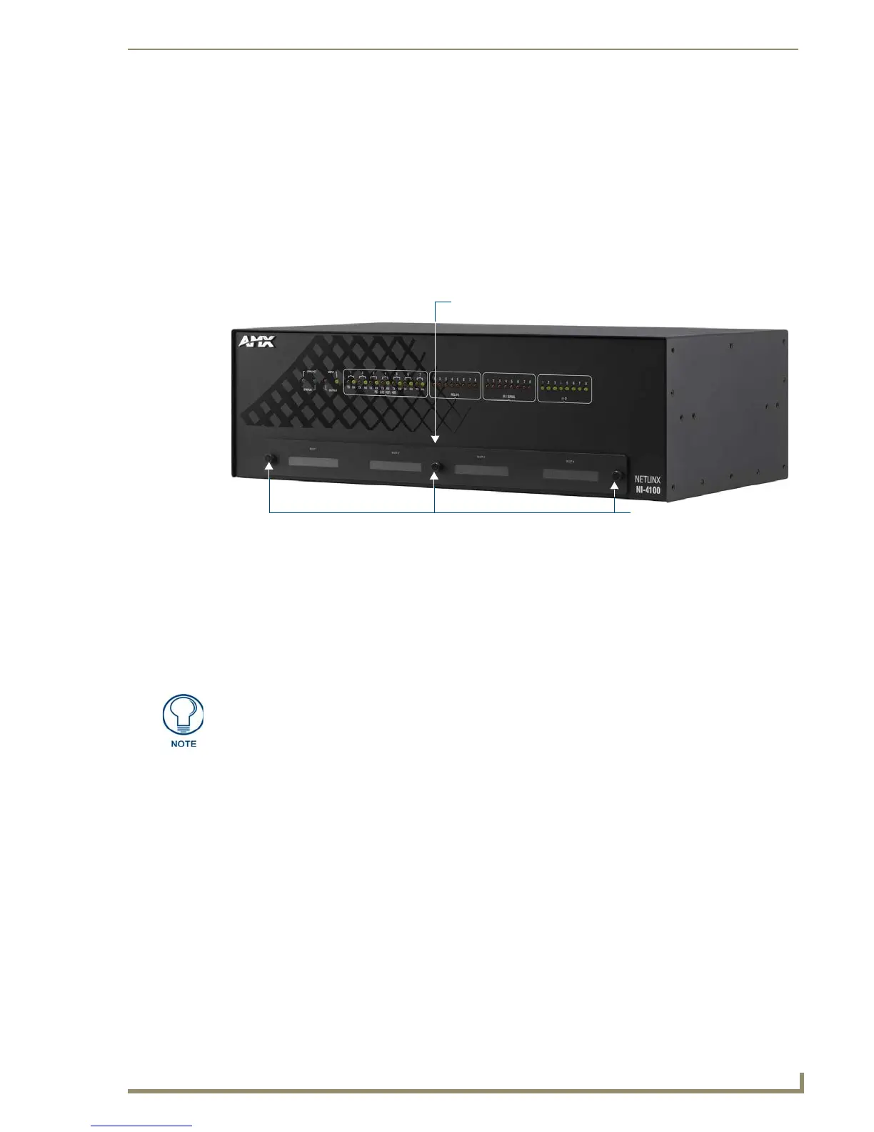
2. Remove the three screws by turning them in a counter-clockwise direction and then remove the faceplate
(FIG. 4).
3. Align the edges of the card with the internal guide slots and gently slide the card all the way into the slot.
4. Carefully apply a small amount of force to insert the cards into their respective connectors. If the cards
have LEDs on them, those LEDs will initiate a lighting sequence to indicate they are receiving power and
are communicating with the Controller.
5. Re-align the faceplate and secure it to the chassis by inserting the three screws by turning them in a
clockwise direction and securing the front plate to the Integrated Controller.
6. Install all rear connectors and apply power.
Setting the NetLinx Control Card Addresses (NI-4100 Only)
The 8-position CardFrame Number DIP switch (located on the rear of the NI-4100) sets the starting address
(the device number in the D:P:S specification) for the Control Cards installed in the CardFrame. The address
range is 1-3064.
The factory default CardFrame DIP switch value = 0 (all CardFrame DIP switches in the OFF
position).
The formula for setting the starting address is:
(DIP switch address x 12) + Card slot Number (1-12) = Card address
For example:
DIP switch setting, 00010101: (0 + 0 + 0 + 96 + 0 + 384 + 1536) + SLOT # (ex:1) = 2017.
A card in slot number 1 would be device address 2017.
FIG. 4 NI-4100 front faceplate
Thumbscrews
NXC Card Slot faceplate
If the cards do not appear in the NetLinx Studio’s Workspace window for the selected
Master System number: give the system time to detect the inserted cards (and
refresh the system) and/or cycle power to the unit.

 Loading...