Connections and Wiring
27
NI-2100, NI-3100, NI-4100 Hardware Reference Guide
ICSHub OUT Port: Connections and Wiring
The NI Controller must be equipped with the available ICSNet connectors for this functionality to be active.
The following table describes the pinout/signal information for the ICSHub OUT port located on the rear panel
of the Integrated Controller.
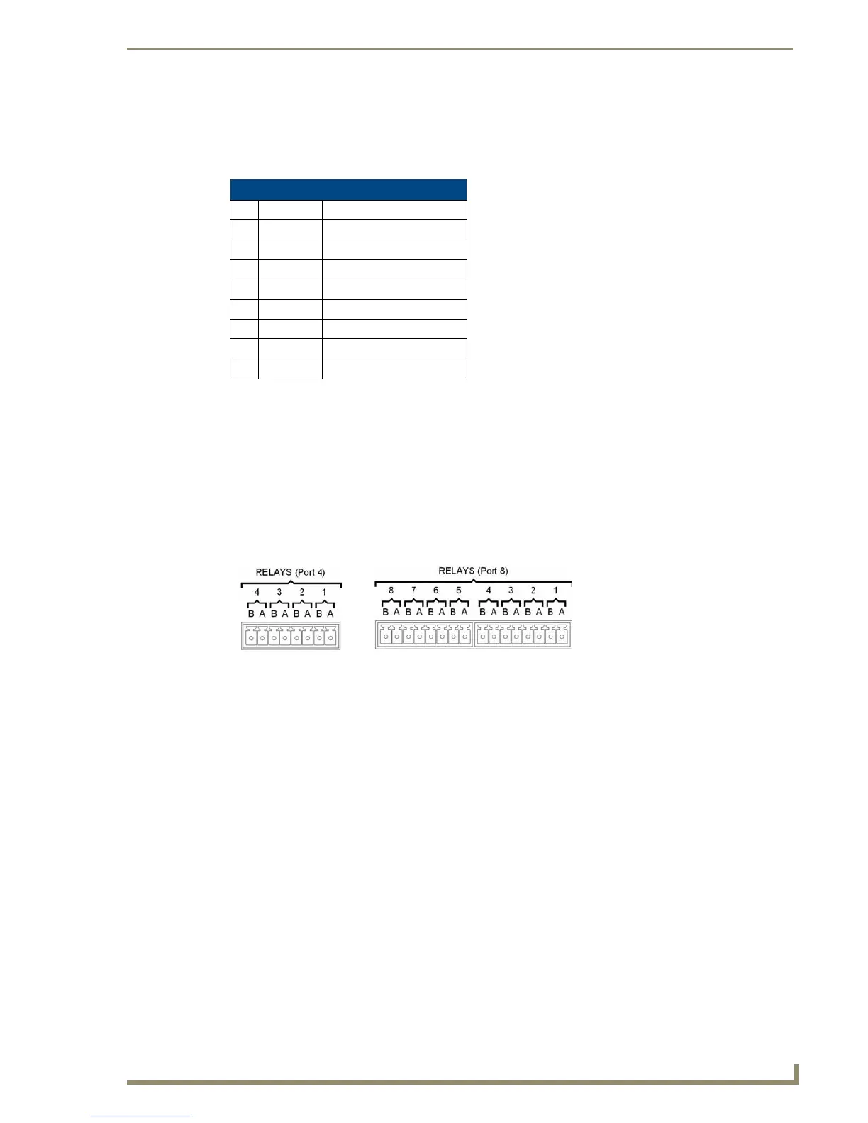
Relay Port: Connections and Wiring
You can connect up to 8 independent external relay devices on both the NI-4100 and NI-3100 units (4 on the
NI-2100) to the Relay connectors on the Integrated Controller.
Connectors labeled A are for common; B are for output.
Each relay is isolated and normally open.
A metal commoning strip is supplied with each Integrated Controller to connect multiple relays.
Relay Connections
Use A for common and B for output (FIG. 13). Each relay is isolated and normally open. A metal connector
strip is also provided to common multiple relays.
ICSHub OUT Pinouts and Signals
Pin Signal Color
1 RX + orange-white
2 RX - orange
3 ------ ------
4 ------ ------
5 ------ ------
6 ------ ------
7 TX + brown-white
8TX -brown
FIG. 13
RELAY connector (male)
NI-4100/NI-3100 relay connector
configuration (Port 8)
NI-2100 relay connector
configuration (Port 4)

 Loading...